



Control valve · Pneumatic actuator
C1 control valve with pneumatic actuator
Modulating or ON/OFF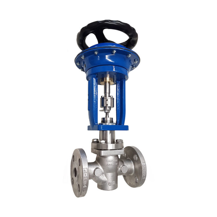
Single-seat, top-entry globe control valve operated by a multi-spring pneumatic diaphragm actuator. It regulates gases, vapors, and liquids in modulating or ON/OFF service, from DN15 to DN100 and up to PN40.
- SizesDN15 to DN100 DN125 and DN150 on request
- Pressure ratingPN25 bronze · PN40 steel
- Standard Kv3.5 to 130 m³/h
- CharacteristicEqual-percentage, linear, or ON/OFF
- Temperature−5 to +200 °C up to 350 °C depending on bonnet and packing
- Control airup to 4 barg
Questions about selecting the Kv or the actuator? Call 933 720 888 or email valfonta@valfonta.com.
- In-house design and manufacturing in Badalona
- ISO 9001 certified quality system
- Version with ATEX II 2 GD marking
- Actuator factory-calibrated to your data
What the C1 is used for
The C1 is a control valve: the plug changes position according to the air signal the actuator receives from the control system. It requires instrument air and a control signal, and in return it is operated from the process control system, in continuous or on/off control.
Its modular design combines plugs, bonnets, packings, leakage classes, and four actuator sizes. Learn more about the types of control valves and Valfonta’s control valve design.
- Modulating controlEqual-percentage or linear plug, positioned according to the process signal.
- ON/OFF serviceON/OFF plug for full opening and closing.
- Steam and high temperatureFinned bonnet for over 200 °C and graphite packing up to 350 °C.
- Low temperatureExtended bonnet for fluids below −5 °C.
- Explosive atmospheresATEX II 2 GD version and 4–20 mA electro-pneumatic positioner (Ex).
C1 technical specifications
| Type | Globe, two-way, single seat, top entry, guided plug |
|---|---|
| Connections | EN 1092-1 Type B1 flanges · ANSI 150/300 · On request: BSP or NPT thread, BW or SW |
| Body and pressure rating | PN25: RG-10 bronze (EN 1982 CuSn10-CC480K) · PN40: GP240GH / A216 WCB (1.0619) carbon steel · PN40: CF3M (1.4408) stainless steel |
| Fluids | Gases, vapors, and liquids |
| Flow characteristic | Equal-percentage, linear, or ON/OFF |
| Kv coefficient | 3.5 (DN15) to 130 m³/h (DN100). Reduced Kv and bore on request |
| Leakage class | Class IV (metal-to-metal) · Class VI (PTFE+graphite plug). On request: PEEK, NBR, EPDM, stellited seat |
| Bonnet | Standard: −5 to +200 °C · Finned: over +200 °C · Extended: below −5 °C · With bellows: on request |
| Stem sealing | Standard: double PTFE+graphite V-ring, up to +200 °C · PTFE: up to +150 °C · Graphite: up to +350 °C · Bellows: on request |
| Actuator | Multi-spring diaphragm, reversible in-line: HF.205, HF.275, HF.360, and HF.430 (10 to 25 kg). Steel 1.0335 with epoxy paint and fabric-reinforced EPDM diaphragm |
| Control air | Up to 4 barg, ¼″ BSP female connection, dry air free of oil and water |
| Control signals | 0.2–1 · 0.4–1.2 · 0.4–2 · 1.5–3.2 bar, depending on actuator |
| Fail-safe position | Normally closed or normally open |
| Options | Electro-pneumatic positioner (Ex) 4–20 mA or smart positioner, filter regulator, handwheel, solenoid valve, alarm contacts, stainless steel construction, anti-cavitation and low-noise cage. NAMUR mounting (IEC 534-6) |
| Pressure equipment | The nameplate indicates whether it carries CE marking under PED 2014/68/EU. Declaration of conformity on request |
| ATEX | II 2 GD c IIC Tx / c IIIC TxºC · certificate LOM 14.034 U |
Dimensions, weight, and Kv
| DN15 | DN20 | DN25 | DN32 | DN40 | DN50 | DN65 | DN80 | DN100 | |
|---|---|---|---|---|---|---|---|---|---|
| Kv (m³/h) | 3,5 | 5 | 9 | 15 | 22 | 35 | 60 | 85 | 130 |
| Cv (gpm) | 4 | 5,8 | 10,4 | 17,5 | 25 | 41 | 70 | 100 | 152 |
| Stroke (mm) | 20 | 20 | 20 | 20 | 20 | 20 | 30 | 30 | 30 |
| Length A (EN 558-1) | 130 | 150 | 160 | 180 | 200 | 230 | 290 | 310 | 350 |
| Length A (ANSI 150) | ○ | ○ | 184 | – | 222 | 254 | 276 | 298,5 | 352,5 |
| Length A (ANSI 300) | ○ | ○ | 197 | – | 235 | 267 | 292 | 317,5 | – |
| Height L with HF.275 | 330 | 330 | 395 | 395 | 420 | 420 | 455 | 455 | 475 |
| Height L with HF.430 | 360 | 360 | 425 | 425 | 450 | 450 | 485 | 485 | 505 |
| Weight without actuator (kg) | 5 | 6 | 7 | 8 | 12 | 15 | 20 | 25 | 40 |
Dimensions in mm. ○ on request · – not available. Dimensioned drawings in the PDF datasheet.
Available Kv by size (m³/h)
| Size | Standard Kv | Kv on request |
|---|---|---|
| DN15 | 3,5 | 0.1 to 2 |
| DN20 | 5 | 0.1 to 2 · 3.5 |
| DN25 | 9 | 0.1 to 2 · 3.5 · 5 |
| DN32 | 15 | 3,5 · 5 · 9 |
| DN40 | 22 | 3,5 · 5 · 9 · 15 |
| DN50 | 35 | 9 · 15 · 22 |
| DN65 | 60 | 15 · 22 · 35 |
| DN80 | 85 | 22 · 35 · 60 |
| DN100 | 130 | 35 · 60 · 85 |
| DN125 | – | 60 · 85 · 130 · 200 |
| DN150 | – | 85 · 130 · 200 · 260 |
Maximum working pressure by temperature (bar) · EN 12516-1 and EN 1092-2
| Body (PN40 · Class 300) | −10 °C | 50 °C | 100 °C | 150 °C | 200 °C | 250 °C | 300 °C | 350 °C |
|---|---|---|---|---|---|---|---|---|
| A216 WCB (1.0619) carbon steel | 40 | 40 | 36 | 35 | 34 | 33 | 30 | 29 |
| CF3M (1.4408) stainless steel | 40 | 38 | 33 | 30 | 28 | 26 | 25 | 24 |
Exploded view and materials (20 parts)
| No. | Part | Material |
|---|---|---|
| 1 | Body | RG10 bronze · WCB steel · CF3M stainless |
| 2 | Seat | 316L stainless |
| 3 | Guide | 316L stainless |
| 4 | Seat (spare part) | PTFE+graphite · SS316L · on request |
| 5 | Seat holder | 316L stainless |
| 6 | Pin | 316L stainless |
| 7 | Hex screw | 8.8 or A-2 |
| 8 | Stem | 316L stainless |
| 9 | Packing (spare part) | See stem sealing table |
| 10 | O-ring (spare part) | Viton |
| 11 | Locknut | A2-70 stainless |
| 12 | Packing nut | 316L stainless |
| 13 | Actuator assembly nut | Galv. steel 1.1191 |
| 14 | Bonnet | Galv. steel 1.1191 or 316 stainless, depending on bonnet |
| 15 | Washer | 8.8 or A-2 |
| 16 | Bonnet cover | Galv. steel 1.1191 |
| 17 | Stem | 316L stainless |
| 18 | Body gasket (spare part) | Graphite |
| 19 | Guide | 316L stainless + Ni |
| 20 | Pin | 316L stainless |
How the C1 works
The fluid flows through the valve in the direction of the arrow on the body, and the plug position depends on the pressure signal reaching the actuator diaphragm.
- Control signal. The control air pushes on the diaphragm and overcomes the spring force.
- Plug movement. The actuator stem drives the valve stem, and the plug moves toward or away from the seat.
- Regulation. With an equal-percentage or linear plug, the valve modulates according to the signal; with an ON/OFF plug it works in on/off mode.
- Fail-safe position. If the signal or the air supply fails, the springs close the valve (normally closed) or open it (normally open).
- Action reversal. The actuator can be switched quickly from direct to reverse action, in-line.
C1 installation
The manual recommends a bypass with a manual valve so the process can still be controlled by hand while the C1 is isolated for maintenance.
Installation and start-up
- Install isolation valves at the inlet and outlet, a strainer upstream, and a manual bypass valve. Never exceed the pressure or temperature in the specifications.
- Leave 6 × DN clear of obstructions upstream and downstream of the valve, avoid stress and vibration, and leave room to remove the actuator.
- Follow the arrow on the body. A horizontal pipe with the actuator vertical, facing up, is recommended; the manual also allows the actuator to be horizontal or facing down.
- Connect the control air to the ¼″ BSP female port: dry air, free of oil and water, at 4 barg maximum. The control signal is shown on the nameplate.
- Start up slowly: open the isolation valves gradually and check for leaks.
Valfonta supplies the actuator precalibrated to the customer’s requirements; if the stroke needs readjusting, the manual describes the procedure. Actuators with preloaded springs are identified by four longer screws: release them before working on the actuator. In ATEX zones, the electrical resistance between the valve and the installation must be less than 10⁶ Ω. Also review the common mistakes with pressure control valves.
C1 technical documentation
C1 datasheetPDF · 6 pages · features, dimensions, exploded view, Kv, and allowable pressure by actuator
Do you need the declaration of conformity or the ATEX documentation for an order? See our quality certificates.
C1 vs. self-operated reducing valves
The C1 is the only actuated control valve in the range. The M1, M2, and VD reducing valves regulate the outlet pressure with no auxiliary power; the C1 requires control air, but it is operated from the process control system and allows ON/OFF service.
In parentheses: C1 with finned bonnet and graphite packing; VD with EPDM or Viton gaskets. Data from the C1-19A datasheet and the 2025 reducing valve catalog. More criteria in our guide to control valve selection.
Frequently asked questions about the C1
What is the difference between the C1 and a self-operated reducing valve?
The C1 moves the plug with a pneumatic actuator that responds to a control signal, so it requires control air (up to 4 barg). The M1, M2, and VD reducing valves regulate the outlet pressure on their own, with no auxiliary power. We compare them in self-operated valve vs. actuated valve.
What happens if the control air fails?
The valve goes to its fail-safe position, which depends on how the actuator springs are mounted: the normally closed version closes and the normally open version opens.
Can it be controlled with a 4–20 mA signal?
Yes, with the 4–20 mA electro-pneumatic positioner (Ex) or a smart positioner, both available as options. Accessory mounting is NAMUR to IEC 534-6. More on automatic control valves.
Can it be installed in an ATEX zone?
Yes, in its version with ATEX II 2 GD marking (certificate LOM 14.034 U), for zones 1, 2, 21, and 22. The valve must be equipotentially bonded to the installation.
What maintenance does it need?
Wear parts are inspected according to the severity of service, with the body installed, depressurized, and isolated. Recommended spare parts: seat, packing, O-ring, and body gasket; on the actuator, plunger, springs, diaphragm, and O-ring. To order them, give the serial number on the nameplate.
Self-operated alternatives to the C1
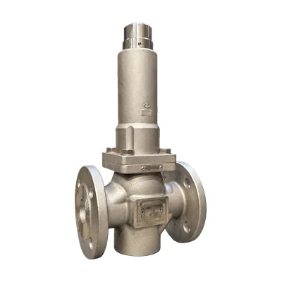
 M1 reducing valveNo auxiliary power, DN15–150, and steam up to 220 °C.
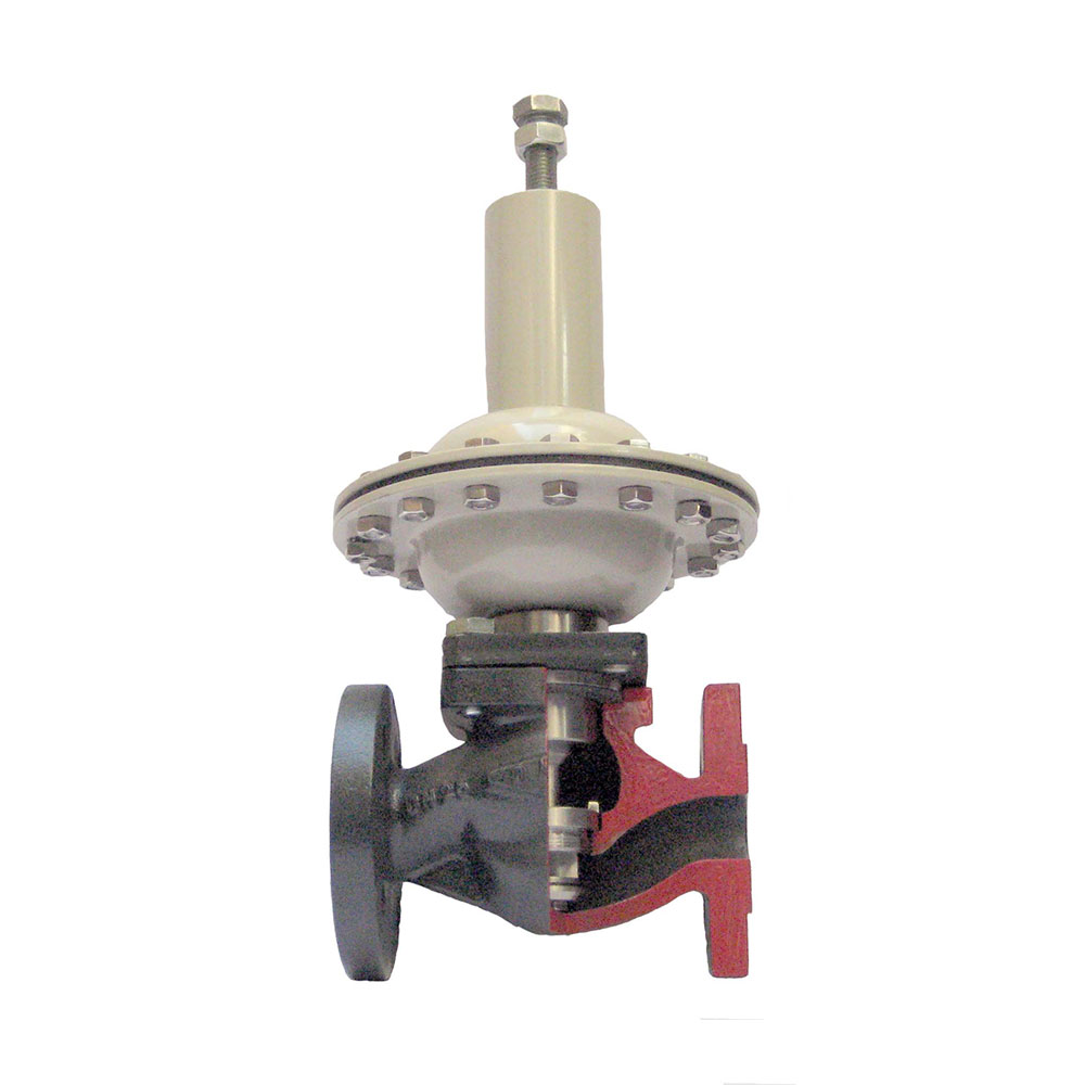 M2 diaphragm reducing valveNo actuator, DN15–100, and outlet pressures from 0.02 barg.
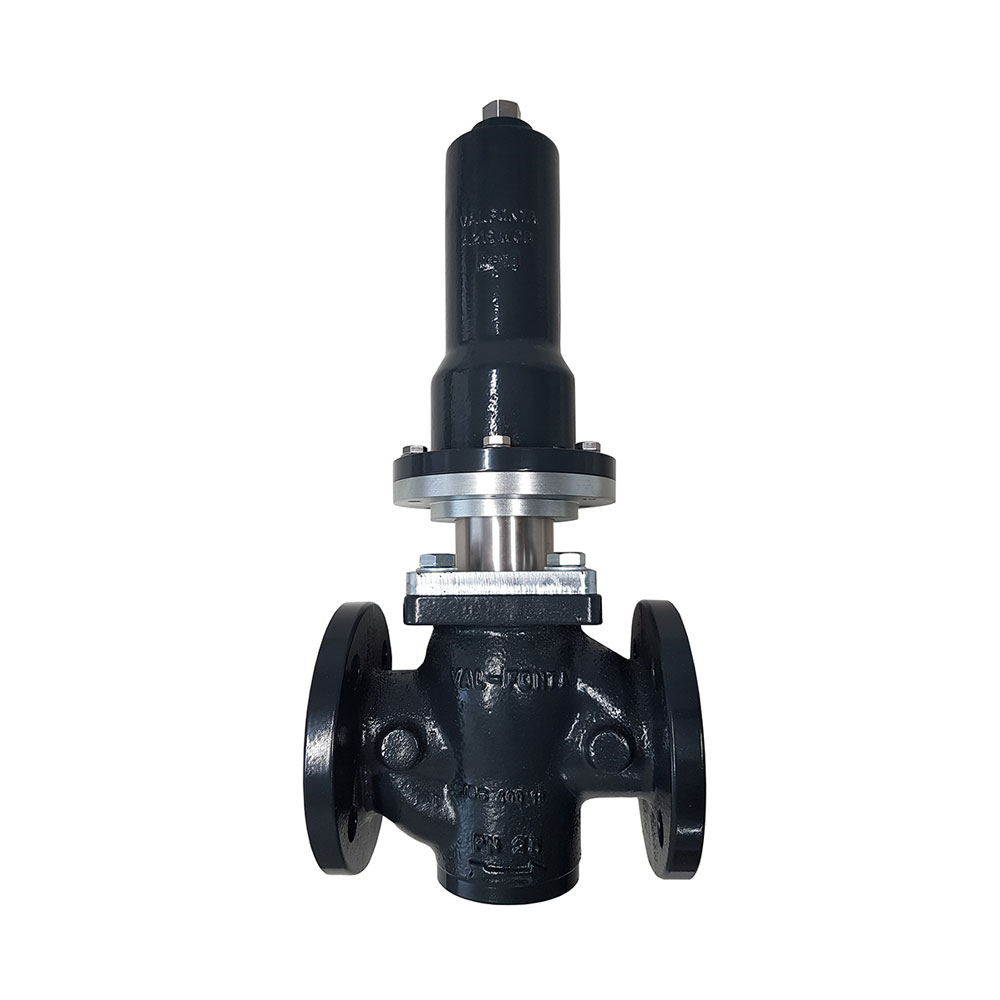 M2 bellows reducing valveSelf-operated with bellows, DN15–50, and steam up to 200 °C.
 VD reducing valvePiston type, DN15–100 and PN40, for steam up to 200 °C, liquids, and gases.
Request a quote for the C1
Give us your process details and we will propose the right size, Kv, plug, and actuator.
- Fluid, operating temperature, and operating pressure
- Inlet and outlet pressures and maximum and minimum flow rates (or Kv)
- Control signal and fail-safe position (NC or NO)
- Body material, connection, and leakage class
You can also call 933 720 888.