


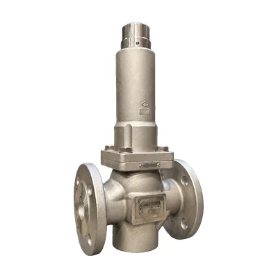

Pressure relief valve · Spring-loaded
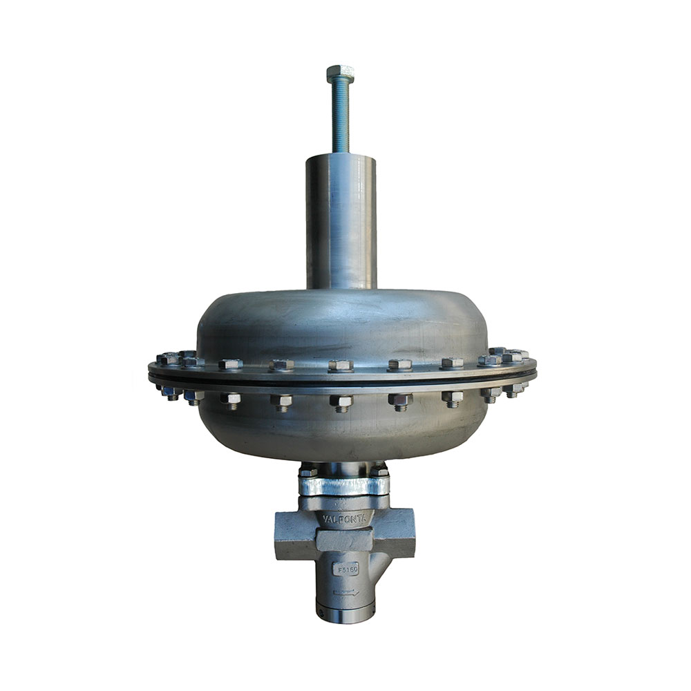
S3 pressure relief valve
Up to 220 °C

The S3 is a direct-acting, spring-loaded pressure relief valve with a guided plug. It holds the upstream pressure at the set value, from 0.5 to 20 barg, on steam, Group 1 and 2 gases, and liquids, up to 220 °C.
- SizesDN15 to DN150 DN125 and DN150 on request
- Pressure ratingPN25 – PN40 Class 150 – 300
- Set pressure0.5 to 20 barg
- Temperatureup to 220 °C 250 °C with special gaskets
- Kv3.5 to 130 m³/h
- Leakage classIV (metal-to-metal) or VI (PTFE+GR)
Questions about set pressure or sizing? Call 933 720 888 or email valfonta@valfonta.com.
- In-house design and manufacturing in Badalona
- ISO 9001 quality system
- Guided plug for greater stability
- Recommended spare parts identified in the exploded view
What the S3 relief valve is used for
The S3 is a pressure relief valve that holds the upstream pressure at the set value: when the inlet pressure exceeds it, the valve opens gradually, in proportion to the pressure rise, and closes again when the pressure returns to normal. It is direct-acting: no auxiliary power, diaphragm, or control line.
The set pressure is determined by a spring, and the guided plug provides stability. It has AISI 316L stainless steel internals and is available with Class VI leakage using a PTFE + graphite seat. If you work with water, read our article on the pressure relief valve for water.
- Pump bypassReturns excess flow to the suction side or to the tank.
- Line and equipment protectionLimits the upstream pressure to the set value.
- SteamUp to 220 °C with PTFE + graphite plug and gaskets.
- Group 1 and 2 gasesProportional relief of excess pressure.
- Water, oil, and other liquidsWith PTFE + graphite, stainless steel, EPDM, NBR, FKM, or PEEK plug.
S3 relief valve technical specifications
| Type | Direct-acting, spring-loaded, with guided plug |
|---|---|
| Sizes | DN15 to DN100; DN125 and DN150 on request |
| Connections | EN and ANSI flanges · BSP or NPT thread from ½″ to 2″ · Weld ends (BW, SW) on request |
| Pressure rating | PN16 – PN25 – PN40 · ANSI Class 150 – Class 300 |
| Set pressure | 0.5 to 20 barg, with different spring ranges |
| Kv coefficient | From 3.5 m³/h (DN15) to 130 m³/h (DN100). Full bore as standard; reduced bore on request |
| Body temperature | Carbon steel: −10 to 220 °C · CF3M stainless: −30 to 220 °C · Up to 250 °C with special gaskets |
| Temperature depending on plug | NBR: 80 °C · EPDM or FPM: 150 °C · PTFE + graphite: 220 °C · PEEK: 250 °C |
| Gaskets and packing | Virgin PTFE up to 180 °C · PTFE + graphite up to 220 °C |
| Leakage class | Class IV (metal-to-metal) · Class VI (PTFE + graphite seat) |
| Fluids | Steam, Group 1 and 2 gases, water, oil, and other liquids |
| Body material | GP240GH (1.0619) carbon steel or A351 CF3M stainless. On request: RG10 bronze, duplex, or super duplex |
| Internals | Stainless steel AISI 316L |
| Options | Handwheel adjustment · PEEK, NBR, EPDM, or stellited plug · Special gaskets |
| Standards | ISO 9001 quality system · PED 2014/68/EU: the nameplate indicates whether CE marking is required |
Dimensions and weight
| DN15 | DN20 | DN25 | DN32 | DN40 | DN50 | DN65 | DN80 | DN100 | |
|---|---|---|---|---|---|---|---|---|---|
| Kv (m³/h) | 3,5 | 5 | 9 | 15 | 22 | 35 | 60 | 85 | 130 |
| Cv (gpm) | 4 | 5,8 | 10,4 | 17,5 | 25 | 41 | 70 | 100 | 152 |
| Length A (EN 558-1) | 130 | 150 | 160 | 180 | 200 | 230 | 290 | 310 | 350 |
| Length A (ANSI 150) | On request | On request | 184 | – | 222 | 254 | 276 | 298,5 | 352,5 |
| Length A (ANSI 300) | On request | On request | 197 | – | 235 | 267 | 292 | 317,5 | – |
| Weight (kg) | 10 | 10 | 12 | 13 | 16 | 18 | 30 | 40 | 50 |
Dimensions in millimeters. Heights, with or without handwheel, are shown in the PDF drawings.
Recommended set pressure ranges
| Range (barg) | DN15 and DN20 | DN25 and DN32 | DN40 and DN50 | DN65 | DN80 | DN100 |
|---|---|---|---|---|---|---|
| 1 – 4 | – | – | Standard | Standard | Standard | Standard |
| 1 – 6 | Standard | Standard | – | – | – | – |
| 3 – 8 | – | – | Standard | Standard | Standard | Standard |
| 4 – 12 | Standard | Standard | Standard | Standard | Standard | On request |
| 8 – 16 | Standard | Standard | Standard | On request | – | – |
| 15 – 25 | On request | On request | On request | – | – | – |
Allowable working pressure by temperature (bar, EN 12516-1 and EN 1092-2)
| Body | −10 °C | 50 °C | 100 °C | 150 °C | 200 °C | 250 °C |
|---|---|---|---|---|---|---|
| PN40 · GP240GH carbon steel | 40 | 40 | 36 | 35 | 34 | 33 |
| PN40 · CF3M stainless | 40 | 38 | 33 | 30 | 28 | 26 |
Exploded view and materials (19 parts)
| No. | Part | Material |
|---|---|---|
| 1 | Body | Carbon steel or A351 CF3M stainless (316L) |
| 2, 3, 5, 6 | Seat, guide, plug holder, and stem | AISI 316L stainless |
| 4 | Plug | PTFE + graphite or 316L stainless; EPDM, NBR, FKM, or PEEK on request |
| 7, 24 | Screws and washer | Zinc-plated steel 8.8 or A2-70 stainless |
| 8, 17 | O-rings | FKM (or NBR, EPDM) |
| 9 | Spring cover | A351 CF3M stainless (316L) |
| 10 | Adjusting spring | Spring steel with epoxy paint |
| 11, 20 | Lower and upper spring supports | Zinc-plated steel 1.1191 |
| 12 | Bearings | PTFE + graphite |
| 13 | Adjusting stem A | AISI 316L stainless |
| 14, 19, 27, 28 | Washer, adjusting stem B, pin, and nut | A2-70 stainless |
| 15 | Cap plug | Zinc-plated steel 1.1191 or 316L stainless |
| 16 | O-ring | FKM (or NBR, EPDM, PTFE) |
| 21 | Flat gasket | PTFE |
| 22 | Flat gasket | Graphite (or PTFE) |
| 23 | Bonnet | AISI 316L stainless |
| 25 | Insulating gasket | PTFE + graphite + 302 stainless |
| 26 | Stem guide | Bronze or 316L stainless + Ni |
| 110 – 116 | Handwheel option components | Painted steel handwheel, 316L stem, plug, and gaskets |
Recommended spare parts
| Reference | Description | Parts |
|---|---|---|
| — | Plug | 4 |
| — | O-rings | 8, 16, and 17 |
| — | Bearings | 12 |
| — | Flat and insulating gaskets | 21, 22, and 25 |
How the S3 relief valve works
The inlet pressure and the spring force balance each other on the plug, with no auxiliary power.
- Valve closed. As long as the force of the inlet pressure (p1) is lower than the spring force, the plug stays on the seat.
- Proportional opening. When the pressure exceeds it, the valve opens in proportion to the pressure rise and relieves the excess fluid.
- Stable regulation. The valve modulates so that the upstream pressure does not exceed the set pressure; the guided plug gives it stability.
- Closing. When the pressure returns to normal, the spring closes the valve again.
- Set pressure. The spring force is adjusted with the adjusting stem (13) or, on the handwheel version, with the handwheel.
A relief valve is not a safety valve; if you need overpressure protection, install both. See the difference between a safety valve and a relief valve.
S3 relief valve installation
In a typical installation, the S3 is mounted on a branch off the main line, for example on a pump bypass, so that the relieved flow returns to the suction side or to the tank. An upstream pressure gauge lets you check the set pressure.
- Pump or equipment that generates the pressure
- Upstream pressure gauge
- S3 relief valve
- Return to the suction side or to the tank
- Main line to the point of use
Installation and start-up
- Protect the valve from dirt and impacts. If you use lifting gear, attach it to the body, never to the adjusting screw.
- Clean the pipe and install a strainer upstream of the valve to protect the seat.
- Follow the arrow on the body and install the valve in a horizontal pipe, which is the recommended position (with a slight slope if condensate is present).
- Support the pipe, not the valve: place supports close to the flanges.
- Start up slowly: open the isolation valves gradually, inlet first, to avoid water hammer.
- Adjust the set pressure if necessary (Valfonta supplies the valve set to the specified pressure): remove the cap plug (15) and the O-ring (16) and turn the adjusting stem (13), or turn the handwheel. Turning clockwise compresses the spring and raises the set pressure. Refit the O-ring and the cap plug.
It must be installed by specialized personnel, without exceeding the design pressure and temperature. See our guide on relief valve set pressure.
S3 technical documentation
To order spare parts, give the serial number (S/N) shown on the nameplate. Order certificates: see our quality certificates.
S3 vs. other relief and excess pressure valves
The range covers DN15 to DN150 and set pressures from 0.01 to 20 barg.
| Model | DN | PN | Set pressure (barg) | Max. T (°C) | Steam | Standard body |
|---|---|---|---|---|---|---|
| PRV53 | 15 – 25 | 25 | 0,5 – 15 | 150 | No | CF3M stainless |
| PRV54 | 15 – 25 | 25 | 0,5 – 12 | 210 | Yes | CF3M stainless |
| PRV55 | 15 – 25 | 25 | 0,01 – 8 | 150 | Yes | CF3M stainless |
| S1 | 15 – 150 | 40 | 0,5 – 15 | 220 | Yes | Carbon steel or CF3M stainless |
| S2 | 15 – 100 | 40 | 0,02 – 10 | 180 | Yes | Carbon steel or CF3M stainless |
| S3 | 15 – 150 | 40 | 0,5 – 20 | 220 | Yes | Carbon steel or CF3M stainless |
| S4 | 15 – 100 | 40 | 0,5 – 20 | 220 | Yes | Carbon steel or CF3M stainless |
Data from the Valfonta summary catalog (2025); S2 set pressure from its datasheet. All accept water, oil, air, and non-flammable gases.
Frequently asked questions about the S3
Does a pressure relief valve replace a safety valve?
No. The S3 relieves excess pressure proportionally, but it is not a safety valve. If the installation needs overpressure protection, a safety valve must also be installed.
What set pressure does the S3 accept?
From 0.5 to 20 barg, with different springs. For example, for DN15 and DN20 the standard ranges are 1 to 6, 4 to 12, and 8 to 16 barg; the 15 to 25 barg range is available on request.
How do you adjust the set pressure?
Remove the cap plug (15) and the O-ring (16) and turn the adjusting stem (13): turning clockwise raises the set pressure and counterclockwise lowers it. With a handwheel, simply turn it.
Can it be used with steam?
Yes. With a PTFE + graphite plug and gaskets it works up to 220 °C, and up to 250 °C with special gaskets or a PEEK plug.
Is it suitable for fire protection systems?
Yes. The S3 has specific approval for fire protection systems, where it is installed on the pump bypass. Ask us for the certificate along with the quote.
How is it installed on a pump bypass?
On a branch off the discharge line that returns to the suction side or to the tank, with an upstream pressure gauge. If the pressure exceeds the set pressure, the S3 opens and returns the excess flow.
Other pressure relief valve models
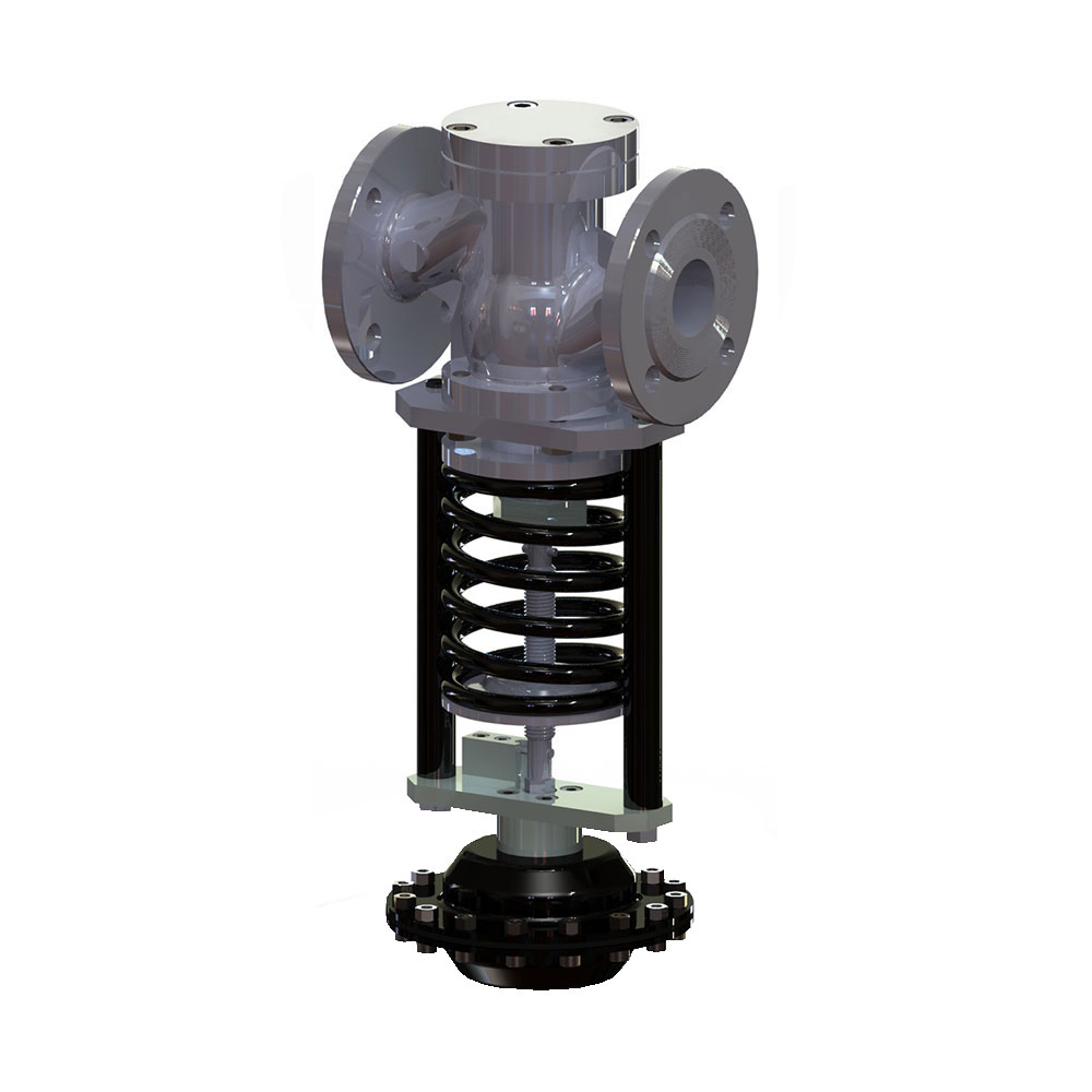 S1 excess pressure valveDiaphragm and bellows, up to DN150 and 220 °C.
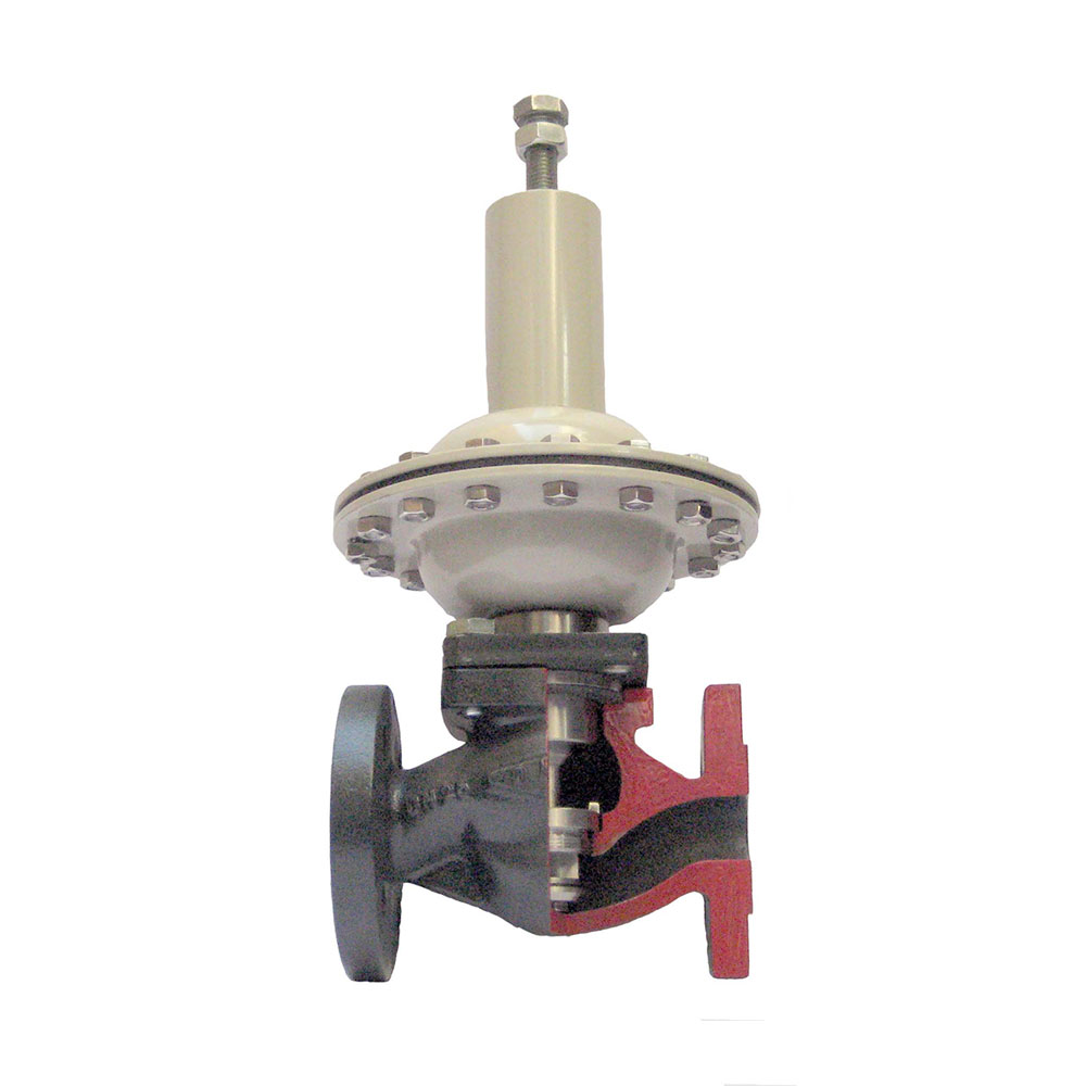 S2 excess pressure valveDiaphragm with internal sensing, set pressure from 0.02 barg.
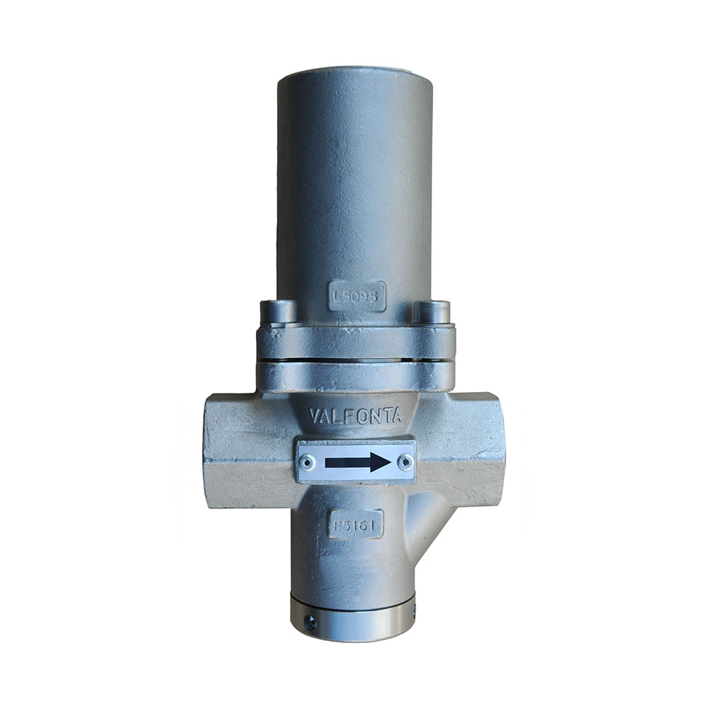 PRV53 excess pressure valveCF3M stainless, DN15 to DN25, set pressure from 0.5 to 15 barg.
- PRV54 excess pressure valveCF3M stainless, DN15 to DN25, steam up to 210 °C.
 PRV55 excess pressure valveSet pressures from 0.01 barg, DN15 to DN25.
Request a quote for the S3
Give us your installation details and we will recommend the right size, spring range, and plug material for your set pressure.
- Fluid and operating temperature
- Set pressure and normal operating pressure
- Flow rate the valve must relieve
- Size, body material, and connection type
You can also call 933 720 888.