


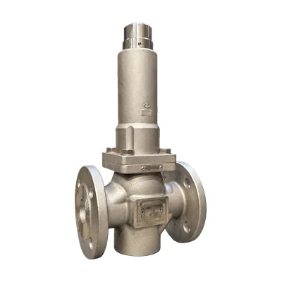

Designed and manufactured in Badalona since 1962
Control valves
They adjust the fluid flow according to the signal from the process control system. The Valfonta C1 is a globe valve with a pneumatic diaphragm actuator for gases, vapors, and liquids, in modulating or ON/OFF service.
- SizesDN15 to DN100 DN125 and DN150 on request
- Pressure ratingPN25 bronze · PN40 steel
- Standard Kv3.5 to 130 m³/h
- Temperature−5 to 200 °C up to 350 °C with suitable bonnet and packing
Questions about the Kv or the actuator? Call 933 720 888 or email valfonta@valfonta.com.
Find the right size for your C1
m³/h
Pipe size
Kv is the flow rate in m³/h that passes through the fully open valve with a 1 bar pressure differential. You will see the sizes that reach it with a standard plug or on request; we will confirm the size with your process data.
- In-house design and manufacturing in Badalona
- ISO 9001 certified quality system
- Version with ATEX II 2 GD marking
- Actuator factory-calibrated to your data
The C1 control valve: sizes and Kv
The C1 is the actuated control valve in the range. Filter by Kv or size in the header. Each size has a standard Kv and accepts smaller Kv values on request.
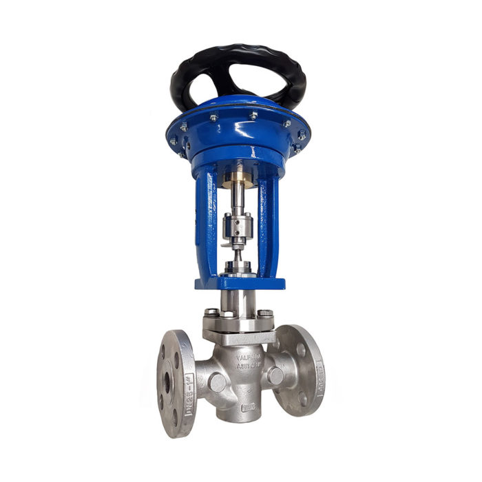
Globe · pneumatic actuator
C1
Two-way globe valve with multi-spring pneumatic diaphragm actuator, for gases, vapors, and liquids.
Sizes
DN15 to DN100 DN125 and DN150 on request
Standard Kv
3.5 to 130 m³/h
Pressure rating
PN25 bronze · PN40 steel
Temperature
−5 to 200 °C up to 350 °C depending on bonnet
Choose it if the valve must be driven by an external signal, pneumatic or 4–20 mA with a positioner, and needs a defined fail-safe position if the air supply fails.
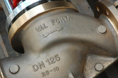
On request
Custom design
If the standard C1 does not fit your process, we study the application and adapt the valve.
Sizes
DN125 and DN150
Kv
reduced or special
Connections
threaded, BW, or SW
Internals
anti-cavitation and low-noise cage
| DN15 | 3,5 | 0.1 to 2 | 4 | 20 | 5 |
|---|---|---|---|---|---|
| DN20 | 5 | 0.1 to 2 · 3.5 | 5,8 | 20 | 6 |
| DN25 | 9 | 0.1 to 2 · 3.5 · 5 | 10,4 | 20 | 7 |
| DN32 | 15 | 3,5 · 5 · 9 | 17,5 | 20 | 8 |
| DN40 | 22 | 3,5 · 5 · 9 · 15 | 25 | 20 | 12 |
| DN50 | 35 | 9 · 15 · 22 | 41 | 20 | 15 |
| DN65 | 60 | 15 · 22 · 35 | 70 | 30 | 20 |
| DN80 | 85 | 22 · 35 · 60 | 100 | 30 | 25 |
| DN100 | 130 | 35 · 60 · 85 | 152 | 30 | 40 |
| DN125 | – | 60 · 85 · 130 · 200 | – | – | – |
| DN150 | – | 85 · 130 · 200 · 260 | – | – | – |
All sizes from DN15 to DN100 are made in RG-10 bronze (PN25), carbon steel, or CF3M stainless steel (PN40). DN125 and DN150 on request only. Data from datasheet C1-19A; dimensions and heights with actuator in the C1 datasheet.
No C1 size covers that Kv. Valfonta adapts models and designs custom valves: tell us about your application in the form or see the custom design service.
C1 options and configuration
It is a modular design: the same body accepts different plugs, bonnets, packings, leakage classes, and four actuator sizes. These are the options listed in its datasheet:
| Plug characteristic | Equal-percentage or linear for modulating control; ON/OFF for on-off service. Guided plug |
|---|---|
| Leakage class | Class IV, metal-to-metal · Class VI, PTFE + graphite plug · On request: PEEK, NBR, EPDM, or Stellite-faced |
| Bonnet | Standard, from −5 to +200 °C · Finned, for over +200 °C · Extended, for below −5 °C · With bellows, on request |
| Packing | Double PTFE + graphite V-ring, up to +200 °C (standard) · PTFE V-rings, up to +150 °C · Graphite, up to +350 °C · Bellows, on request |
| Actuator | Multi-spring pneumatic diaphragm actuator in four sizes (HF.205, HF.275, HF.360, and HF.430), reversible in line from direct to reverse action |
| Fail-safe position | Normally closed (closes on air failure) or normally open (opens on air failure) |
| Control signal | 0.2–1 · 0.4–1.2 · 0.4–2 · 1.5–3.2 bar, depending on actuator. Control air up to 4 barg |
| Positioner and accessories | 4–20 mA electropneumatic positioner (Ex) or smart positioner, air filter regulator, manual handwheel, alarm contacts. NAMUR mounting (IEC 534-6) |
| Body and connections | RG-10 bronze (PN25), GP240GH / A216 WCB carbon steel, or CF3M stainless (PN40). EN 1092-1 or ANSI 150/300 flanges; on request, BSP or NPT thread, BW, or SW |
| Special designs | Reduced port, anti-cavitation and low-noise cage, stainless steel construction |
How a control valve works
A control valve works as a variable-area restriction: it adjusts the pressure drop of the fluid according to the signal from a controller. It regulates the flow and, through it, other process variables such as pressure, temperature, or level.
The C1 control valve has a two-way, single-seat globe body with top access to the internals (top entry) and a guided plug. It is driven by a multi-spring pneumatic diaphragm actuator: the control air pushes on the diaphragm and overcomes the spring force, and the actuator stem drives the valve stem to move the plug toward or away from the seat.
If the air or the signal fails, the springs move the valve to its fail-safe position: closed in the normally closed version and open in the normally open version. The actuator can be switched from direct to reverse action in line. See the types of control valves.

Control valve or self-operated reducing valve
There are two ways to hold a stable downstream pressure. Valfonta pressure reducing valves are self-operated: a spring and the fluid's own pressure move the plug, with no air or electricity. The C1 needs instrument air and a control signal, but it is driven from the control system. We explain it in self-operated valve vs. actuated valve.
- Setpoint from the process control systemThe C1: the pneumatic or 4–20 mA signal (with positioner) changes the plug position.
- ON/OFF serviceThe C1 with an ON/OFF plug opens and closes fully according to the signal.
- Defined position on air failureThe C1 in its normally closed or normally open version.
- No instrument airA self-operated reducing valve: the M1 (DN15–150, steam up to 220 °C) or the M2 (DN15–100).
- Very low outlet pressureThe M2 reducing valve regulates from 0.02 barg without an actuator.
- Water, air, and inert gasesThe VD piston reducing valve, from DN15 to DN100 and up to 40 barg inlet pressure.
Standards and certificates
PED 2014/68/EU
The nameplate on each C1 indicates whether it carries CE marking; the declaration of conformity is available on request. Quality system certified to Module D1.
ATEX II 2 GD
Version for zones 1 and 2 (gases) and 21 and 22 (dust). The valve must be equipotentially bonded to the installation.
ISO 9001:2015
Design, manufacture, and sale of globe control valves for process control.
Download Valfonta’s certificates.
Frequently asked questions about control valves
What is a control valve?
It is a valve that changes the flow area according to the signal from a controller, to regulate the flow and, with it, the process pressure, temperature, or level. The Valfonta C1 does this with a pneumatic diaphragm actuator.
What is the difference between a control valve and a self-operated reducing valve?
A control valve moves the plug with an actuator that responds to an external signal, so it needs control air (up to 4 barg on the C1). A self-operated reducing valve, such as the M1, the M2, or the VD, holds the outlet pressure using the energy of the fluid itself. See self-operated valve vs. actuated valve.
What data does Valfonta need to size the C1?
The fluid and its temperature, the inlet and outlet pressures, the maximum and minimum flow rates (or the Kv), the control signal, the fail-safe position (NC or NO), the body material, the connection, and the leakage class.
What happens if the control air fails?
The actuator springs move the valve to its fail-safe position: the normally closed version closes and the normally open version opens. When the signal returns, the valve goes back to its operating position.
Can it be controlled with a 4–20 mA signal?
Yes, with the 4–20 mA electropneumatic positioner (Ex) or a smart positioner, both available as options. More on automatic control valves.
What is the maximum operating temperature of the C1?
With standard bonnet and packing, from −5 to +200 °C. With a finned bonnet and graphite packing, up to +350 °C, and with an extended bonnet, below −5 °C. The allowable pressure of the steel body decreases as the temperature rises.
Technical guides on control valves
Other families: Pressure reducing valves · Pressure relief valves · Custom design · Safety valves
Request a quote for a control valve
Give us your process details and we will propose the right size, Kv, plug, and actuator.
- Fluid, operating temperature, and operating pressure
- Inlet and outlet pressures and maximum and minimum flow rates (or Kv)
- Control signal and fail-safe position (NC or NO)
- Body material, connection, and leakage class
You can also call 933 720 888.