


How to prevent “chattering” (vibration) in pressure relief valves
Article contents
What is “chattering” in a pressure relief valve?
In the design of industrial piping systems, relief valves and excess pressure valves are the guardians of structural integrity. In our guide to pressure relief devices, we review the different types.
However, there is an acoustic and mechanical phenomenon that can turn these safety devices into a threat to the plant: chattering.
This term, which in Spanish we usually render as “vibración” or “traqueteo” (rattling), describes an extremely rapid and violent opening and closing cycle that occurs when the valve enters a state of dynamic instability.
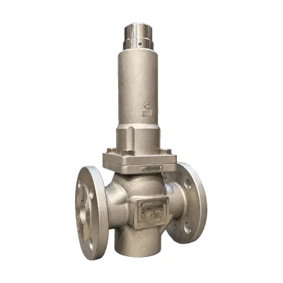
Models such as the Valfonta S1, S2, and S3 series have been refined to deliver a stable response, but even the best engineering can succumb to chattering if the root causes behind it are not understood.
Preventing this phenomenon is not just a matter of acoustic comfort; it is a safety imperative to prevent catastrophic failures, product leaks, and costly unplanned shutdowns.
Understanding chattering and its mechanical risks
Relief valve chattering is not ordinary vibration. It is technically defined as the rapid oscillation of the plug on the valve seat. Unlike smooth regulation, where the plug positions itself in proportion to the detected overpressure, in chattering the moving component repeatedly strikes the metal seat at frequencies that can reach hundreds of hertz.
This behavior is usually the result of an imbalance between the spring force (which tries to close the valve) and the force generated by the fluid pressure (which tries to open it). When these forces fail to find a stable equilibrium point, the valve enters an endless loop of opening-pressure drop-closing-pressure rise, producing a severe mechanical impact in every cycle.
What exactly is chattering, and why does it occur in process lines?
The physics behind chattering is explained by the interaction between the valve and the fluid dynamics of the installation. The cycle begins when the line pressure reaches the set point (set pressure). At that instant, the plug lifts to relieve the excess. However, if there is an excessive pressure drop in the inlet pipe, the pressure sensed by the valve suddenly drops below its reseating value (blowdown).
As a result, the spring forces the plug to close immediately. Once closed, the flow stops, the pressure at the inlet recovers instantly, and the cycle repeats violently. The main causes of this imbalance are usually:
- Inlet pipes that are too long or too narrow: They generate a pressure loss greater than the valve differential.
- Oversizing: If the valve is too large for the flow to be relieved, it opens and empties the line so quickly that the pressure drops before the valve can stabilize.
- Blowdown setting: Too narrow a margin between the opening and reseating pressures encourages instability. It should be reviewed at every relief valve set pressure audit.
The impact of high-frequency oscillations on the service life of internal components
The damage caused by chattering is cumulative and often irreversible. In high-precision models such as the Valfonta S1, which uses diaphragms and bellows for fine regulation, high-frequency vibrations can fatigue the elastic materials in a matter of minutes. The most critical risks include:
Destruction of the seat and plug: Continuous metal-to-metal impact deforms the sealing surfaces, causing permanent leaks (loss of tightness) even when the valve is closed.
Adjusting spring breakage: Vibrations can induce surge waves in the spring, leading to breakage from mechanical fatigue.
Stem galling: Uncontrolled lateral movement during chattering can bend or score the stem, locking the valve in one position (open or closed), which is a critical risk scenario.
Loosening of connections: Vibratory energy is transmitted to the adjacent flanges and piping, potentially causing weld failures or leaks at the gaskets of the main line.
Distinguishing regulation instability from cavitation noise
It is essential that the plant engineer not confuse chattering with other noise phenomena. “Vibrations” are often reported that are actually cavitation. Cavitation occurs when the liquid pressure drops below its vapor pressure, forming bubbles that collapse violently; it sounds as if “stones” were passing through the pipe, but it does not necessarily involve the plug striking the seat.
On the other hand, regulation instability (or “hunting”) is a slow, oscillating movement of the plug as it seeks its position, common when the control loop is not properly tuned. Chattering, by contrast, is violent, high-pitched, and generates physical vibration that can be felt by touching the valve body.
While “hunting” is a precision problem, chattering is a problem of the equipment’s mechanical survival. Correctly identifying this difference makes it possible to apply the right technical solution, whether by adjusting the control sensing point on an S2 or by checking the plug guiding on an S3.
Technical comparison of Valfonta solutions against vibration
To mitigate the risk of instability, Valfonta has developed different excess pressure valve architectures that adapt to the severity of the process and the nature of the fluid.
There is no single solution for chattering, but rather a suitable valve for each pressure and flow scenario. While the S1 series stands out for its sensitivity, the S2 and the S3 offer solutions based on mechanical robustness and remote impulse sensing.
Below is a technical table summarizing the capabilities of these three series in terms of operational stability:
| Technical feature | S1 Series (Diaphragm) | S2 Series (Balanced) | S3 Series (Piston) |
|---|---|---|---|
| Size Range | DN 15 to DN 150 | DN 15 to DN 100 | 1/2″ to 2″ (Threaded/Flanged) |
| Pressure Rating (PN) | PN 16 / 25 / 40 | PN 16 / 25 / 40 | PN 16 / 25 / 40 |
| Sensing Element | Elastomer diaphragm | Piston or diaphragm | Metal piston |
| Anti-Vibration System | Balancing bellows | External impulse sensing | Guided plug |
| Recommended Fluid | Steam and Gases (High Sensitivity) | Liquids and Steam (High Load) | Water, Air, and Oils |
| Relief Accuracy | Very High (± 2-5%) | High (± 5-10%) | Standard (± 10-15%) |
The role of balanced design and the anti-rotation bellows in the S1 model
The S1 series is Valfonta’s answer for applications that require surgical precision, especially in saturated steam and gas service. Relief valve chattering in this model is prevented by a combination of a large sensing area and an internal balancing system.
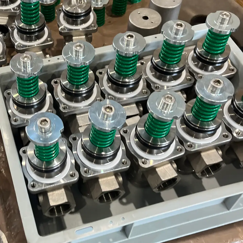
The use of a large-diameter diaphragm allows the valve to detect minimal pressure variations. However, in valves of this type, the outlet pressure (back pressure) could interfere with the movement of the plug, causing oscillations. To prevent this, the S1 incorporates a stainless steel bellows that acts as a balancing element.
This bellows cancels out the upward forces caused by the discharge pressure, ensuring that the plug moves only in response to the inlet pressure we want to relieve. In addition, the bellows drastically reduces mechanical friction, eliminating the hysteresis that often triggers low-frequency vibrations before they develop into violent chattering.
Optimizing the tapping system and external control sensing point in the S2 series
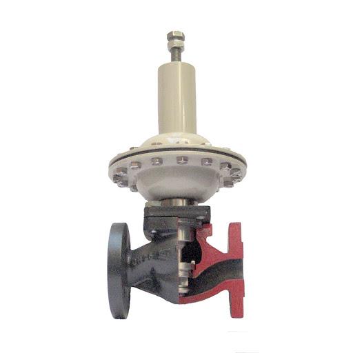
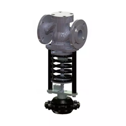
The Valfonta S2 series is known for its versatility and its ability to operate in conditions where the fluid may be more turbulent. One of the biggest advances in preventing chattering in this series is the option of using an external control sensing point (or impulse sensing point).
When a relief valve takes its pressure signal directly from its own body (internal sensing), it is exposed to the turbulence and velocity fluctuations that occur right at the valve seat. This turbulence can “fool” the actuator, making the plug vibrate. By connecting the control sensing point of the Valfonta S2 to a point on the pipe located a prudent distance away (at least 10 times the nominal diameter), the actuator receives a stable, laminar pressure signal.
This design is vital in installations with positive displacement pumps or where the relief flow is very close to the valve’s critical stability point.
Dynamic stability and guided plug: the keys to the S3’s performance
For smaller sizes and more straightforward applications, the S3 model offers a solution based on mechanical rigidity. Chattering occurs not only because of unstable pressure signals, but also because of lateral displacement of the stem when the flow pushes it asymmetrically.
The S3 series mitigates this risk with a guided plug system. Unlike other low-cost valves where the plug “floats” slightly, in the S3 the moving assembly is guided with tight tolerances inside the valve body.
This guiding ensures that contact between the plug and the seat is always perfectly concentric. By eliminating lateral play, it removes the possibility of the plug entering mechanical resonance with the fluid, one of the most common causes of high-pitched noise and premature wear in small relief valves.
Its construction in stainless steel or carbon steel (WCB) ensures that, even if small oscillations occur, the material withstands the mechanical stress without immediate plastic deformation.

Engineering guide to a vibration-free installation
Even the best-built valve, such as the Valfonta S1, S2, or S3 models, can become unstable if the design of the surrounding piping does not respect the basic principles of fluid dynamics.
Relief valve chattering is, in most cases, a system problem rather than a product defect. The key to quiet, long-lasting operation lies in matching the valve capacity to the volume of fluid the line can supply without critical pressure drops.
A professional installation should treat the relief valve as part of a dynamic control loop. If the inlet pipe is too long or has too many fittings (elbows, tees, dirty strainers), the accumulated pressure loss will prevent the valve’s sensor from receiving a true signal of the plant pressure, triggering the dreaded rapid opening and closing cycle.
Correct Kvs sizing and strategic location of the control sensing point
The most common mistake in process engineering is oversizing the valve “to be safe.” An excess pressure valve with an excessive Kvs (flow coefficient) will open only a fraction of its stroke to relieve the excess, emptying the pipe so quickly that the pressure will drop below the reseating point in milliseconds.
This triggers chattering immediately. The valve must be sized for the actual relief flow, not for the diameter of the existing pipe.
As for the control sensing point or impulse line, which is especially critical in the S2 series, its location determines the stability of the entire system. It must be connected on a straight run of pipe, away from turbulent zones such as pumps or control valves. A distance of 10 times the nominal diameter (DN) upstream of the relief point is recommended.
In addition, the impulse line must have an adequate slope to prevent the buildup of condensate or air bubbles that dampen or distort the pressure signal, which could induce erratic vibration in the diaphragm.
Frequently asked questions
Why is an oversized valve the main cause of vibration?
When a valve is too large, its relief capacity far exceeds the system’s surplus flow. When it opens, it discharges the fluid so massively and suddenly that the line pressure instantly drops below the reseating set point. The valve slams shut, the pressure rises again as the flow stops, and the cycle repeats. This “excess capacity” phenomenon is the number one trigger of relief valve chattering.
How does the length of the inlet pipe affect the chattering cycle?
The pipe connecting the main line to the relief valve acts as an accumulator of pressure loss. According to international standards (such as API 520), the pressure loss in the inlet pipe should not exceed 3% of the set pressure.
If the pipe is very long, when the valve opens, the pressure at its inlet drops due to the friction of the moving fluid. The valve “thinks” the plant pressure has fallen and closes, causing mechanical oscillation.
What benefit does a needle valve in the control line provide in stabilizing the pressure?
In models with external impulse sensing such as the S2, installing a small needle valve in the control line makes it possible to “throttle” the pressure signal. By closing the needle slightly, the transient pressure peaks and high-frequency turbulence reaching the actuator are dampened.
It is a form of mechanical filtering that smooths the diaphragm’s response, preventing the plug from reacting violently to minor flow disturbances.
When is a condensate pot needed to protect the actuator?
In high-temperature steam service or with aggressive chemical fluids, the use of a condensate pot (or seal pot) in the control line is vital to protect the diaphragm of the S1 or S2 series.
The pot ensures that the actuator is always in contact with a cold liquid (condensate) and not with live steam or hot gases that could degrade the elastomer. An actuator damaged or hardened by heat loses its damping capacity, making vibrations more likely.
Is chattering an indicator of imminent wear on the seat and plug?
Absolutely. Chattering is not just a noise problem; it is a process of mechanical hammering. Every time the plug strikes the seat during vibration, micro-deformations occur on the sealing surfaces.
In just a few minutes of severe chattering, a new valve can completely lose its tightness, becoming marked (pitting) and requiring lapping or complete replacement of the internals. If you detect chattering, you must intervene immediately to prevent the destruction of the equipment.
How does the S3’s guided plug design help reduce mechanical noise?
The guided plug of the S3 series forces the stem to move strictly axially. In many standard valves, turbulent flow can push the plug sideways, causing it to strike the edges of the seat or vibrate for lack of support.
Valfonta’s precision guiding eliminates this lateral “play,” ensuring that the fluid’s energy is translated into controlled vertical movement rather than mechanical resonances that generate high-pitched noise and frictional wear.
Related valves
Related articles


Can we help with your installation?
Tell us the fluid, the inlet and outlet pressures, the temperature, and the flow rate, and we will recommend the right valve.
You can also call 933 720 888 or email valfonta@valfonta.com.