
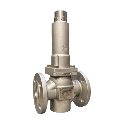

Pressure reducing valve · Bellows-balanced
PRV44 pressure reducing valve
For steam
Self-regulating, direct-acting reducing valve, balanced by a stainless steel bellows and made of AISI 316L. It keeps the outlet pressure constant even when the inlet pressure fluctuates, in steam, water, compressed air, and gases, from −30 to 210 °C.
- SizesDN15 to DN25
- Pressure ratingPN25
- Inlet pressureup to 25 barg
- Outlet pressure0.5 to 12 barg
- Temperature−30 to 210 °C
- Kv2 to 3.5 m³/h
Configure your valve
Questions about sizing? Call 933 720 888 or email valfonta@valfonta.com.
- In-house design and manufacturing in Badalona
- ATEX II 2 GD marking for zones 1 and 21
- Microplasma-welded stainless steel bellows
- Genuine spare parts available, bellows included
What the PRV44 is used for
The PRV44 is a direct-acting pressure reducing valve: it needs no auxiliary power or pilot line. The adjusting spring opens the valve and the outlet pressure closes it; a microplasma-welded stainless steel bellows balances the closing assembly. With its graphite-filled PTFE seat, it handles temperatures up to 210 °C and is suitable for reducing steam pressure in small sizes.
It shares sizes, connections, Kv, and dimensions with the PRV30, so it can replace it when the line carries steam. Its internal design allows efficient fluid flow, and it requires very little maintenance.
- Steam installationsSteam networks and heat exchangers.
- DistilleriesSteam supply at regulated pressure.
- VulcanizingVulcanizing cylinders and presses.
- Dry cleaners and laundriesSteam pressing and laundry equipment.
- Ovens and autoclavesStabilizing the supply pressure.
- Laboratories and industryChemical laboratories, sanitary installations, compressed air, and fuel oil.
PRV44 technical specifications
| Type | Self-regulating, direct-acting, bellows-balanced pressure reducing valve |
|---|---|
| Sizes | DN15 (½″), DN20 (¾″), and DN25 (1″) |
| Connections | BSP or NPT thread · EN PN16/25 flanges · ANSI CL150 flanges |
| Pressure rating | PN25 |
| Maximum inlet pressure | 25 barg |
| Outlet pressure ranges | 0.5 – 3 barg · 1 – 8 barg · 4 – 12 barg (depending on spring) |
| Kv coefficient | 2 m³/h (DN15) · 2.5 m³/h (DN20) · 3.5 m³/h (DN25). Reduced Kv on request |
| Temperature | −30 to +210 °C |
| Fluids | Group 2 liquids and gases: steam, water, compressed air, nitrogen, fuel oil, gases |
| Materials | Body, cap, internals, and bellows in AISI 316L stainless steel. Graphite-filled PTFE seat and PTFE gaskets |
| Bellows | Stainless steel, microplasma-welded |
| Mounting position | Recommended in a horizontal pipe; the design allows other positions |
| Pressure Equipment Directive | PED 2014/68/EU: CE marking not required |
| ATEX | II 2 GD c IIC Tx / c IIIC TxºC · certificate LOM 14.034 U |
| On request | Body and cap in super duplex · weld ends (socket weld or butt weld) · clamp connection · degreased for oxygen service · EPDM, PEEK, Viton, or Aflas gaskets |
Dimensions and weight
| ½″ threaded | ¾″ threaded | 1″ threaded | DN15 EN | DN20 EN | DN25 EN | DN15 ANSI | DN20 ANSI | DN25 ANSI | |
|---|---|---|---|---|---|---|---|---|---|
| Kv (m³/h) | 2 | 2,5 | 3,5 | 2 | 2,5 | 3,5 | 2 | 2,5 | 3,5 |
| Length A / AA | 108 | 108 | 108 | 130 | 150 | 160 | 184 | 184 | 184 |
| Height H1 | 135 | 135 | 135 | 135 | 135 | 135 | 135 | 135 | 135 |
| Height H2 | 185 | 185 | 185 | 185 | 185 | 185 | 185 | 185 | 185 |
| Flange Ø D1 | – | – | – | 95 | 105 | 115 | 89 | 98 | 108 |
| Weight (kg) | 3,5 | 3,5 | 3,5 | 5 | 5 | 5 | 5 | 5 | 5 |
Dimensions in millimeters. The dimensioned drawings and the remaining flange dimensions are in the PDF datasheet.
Exploded view and materials (19 parts)
| No. | Part | Material |
|---|---|---|
| 1 | Body | Stainless steel AISI 316L |
| 2 | Sealing screw | AISI 316L |
| 3 | Seat | Graphite-filled PTFE |
| 5 | Seat | AISI 316L |
| 6 | Gasket (x2) | PTFE |
| 7 | Cap | AISI 316L |
| 8 | Spring washer | Galvanized steel 1.1191 |
| 9 | Adjusting screw | Stainless steel A2-70 |
| 10 | Adjusting spring | Steel 52SiCrNi5 with epoxy paint (60–100 microns) |
| 11 | Bellows screw | AISI 316L |
| 12 | Gasket cover | AISI 316L |
| 13 | Bellows assembly | AISI 316L |
| 14 | Allen screw | Stainless steel A2-70 |
| 15 | Gasket | Graphite-filled PTFE |
| 17 | Stem | AISI 316L |
| 18 | Seat guide | AISI 316L |
| 19 | Closing spring | Stainless steel 302 |
| 21 | Bottom cover | AISI 316L |
| 22 | Gasket | PTFE |
Recommended spare parts
| Reference | Description | Parts |
|---|---|---|
| PRV44.SP2 | Gasket kit | 6 and 22 |
| PRV44.SP3 | Bellows | 13 |
| PRV44.SP4 | Spring kit | 10 and 19 |
| PRV44.SP6 | Gasket and seat kit | 3, 6, 15, and 22 |
How the PRV44 works
The PRV44 works by balancing the forces between the adjusting spring and the outlet pressure. The bellows-stem-seat assembly is what moves to open or close the passage. You can see it in the video.
- Closing by inlet pressure. The fluid enters the valve and, due to the difference in areas, the inlet pressure tends to close it.
- Opening with the spring. When the adjusting spring (10) is compressed with the screw (9), the bellows-stem-seat assembly (13, 17, and 3) opens the valve and allows regulation.
- Regulation. When the outlet pressure exceeds the set value, the valve closes; when it drops, the valve opens again and lets through the flow being consumed.
- Zero flow. If the downstream valves are closed, the PRV44 absorbs the fluctuations and holds the outlet pressure at the set value.
Video of the PRV44 model.
PRV44 installation
This is the layout recommended by the manufacturer, with a bypass so that maintenance can be carried out without interrupting service. If the valve is installed in a bypass, it must be connected to the main pipe after the control line and with its own shutoff valves. See also our guide on how to install a pressure reducing valve.
- Shutoff valves (1, 1a) and bypass valve (1b)
- Strainer
- Inlet pressure gauge
- PRV44 reducing valve
- Safety valve, 0.5–1 m from the reducing valve
- Outlet pressure gauge
Installation and start-up
- Clean the pipe before installing the valve: any debris or impurity can impair the seat.
- Install a strainer upstream to protect the seat.
- Follow the arrow on the body and, whenever possible, install the valve in a horizontal pipe. Some positions are permitted but not recommended, as the valve may not perform well in them.
- Support the pipe, not the valve: supports should be as close as possible to the reducing valve, but never attached to it.
- Leave 0.5 to 1 m of pipe up to the safety valve for better compensation.
- Start up slowly: open the shutoff valves gradually to avoid water hammer.
- Adjust the outlet pressure with an 8 mm Allen key on the adjusting screw. Compressing the spring raises the outlet pressure; releasing it lowers it. Check the value on the outlet pressure gauge.
The valve must be installed by qualified personnel and must never exceed the operating pressure and temperature for which it was sized. In ATEX zones, the valve must be equipotentially bonded to the installation. If the outlet pressure is unstable, review the most common problems with reducing valves.
PRV44 technical documentation
Do you need an order certificate or the ATEX documentation? See our quality certificates or request it from our technical team.
PRV44 vs. other Valfonta reducing valves
Four reducing valves in the range handle steam: PRV44, PRV45, M1, and M2. This table helps you check whether the PRV44 is the right model or whether another one suits you better.
Temperature in parentheses: with EPDM or Viton gaskets. Data from the Valfonta general pressure reducing valve catalog (2025). If you are unsure whether to choose piston, bellows, or diaphragm, read our comparison of piston and diaphragm reducing valves.
Frequently asked questions about the PRV44
Can the PRV44 be used with steam?
Yes. It is its main application: it handles temperatures from −30 to 210 °C and has a graphite-filled PTFE seat. It is also suitable for water, compressed air, nitrogen, fuel oil, and other Group 2 gases.
What is the difference between the PRV44 and the PRV30?
They have the same sizes (DN15 to DN25), connections, Kv, outlet ranges, and dimensions. The PRV30 is piston-balanced and reaches 150 °C with Viton gaskets; the PRV44 is bellows-balanced and reaches 210 °C, so it handles steam.
What outlet pressure can be set?
It depends on the adjusting spring. There are three interchangeable ranges: from 0.5 to 3 barg, from 1 to 8 barg, and from 4 to 12 barg. The inlet pressure can be up to 25 barg.
How do you adjust the outlet pressure?
With an 8 mm Allen key on the adjusting screw. Compressing the spring raises the outlet pressure; releasing it lowers it. We explain it in how to adjust a pressure reducing valve.
What maintenance does it need?
Very little. Check the gaskets and wear parts according to the operating conditions; this can be done with the valve installed, depressurized, and isolated. There are four spare parts: gasket kit (PRV44.SP2), bellows (PRV44.SP3), spring kit (PRV44.SP4), and gasket and seat kit (PRV44.SP6).
Does the PRV44 carry CE marking?
It does not need it. Given its size (DN15 to DN25) and pressure rating (PN25), the Pressure Equipment Directive 2014/68/EU does not require CE marking.
Can it be installed in an ATEX zone?
Yes. The PRV44 carries ATEX II 2 GD marking (certificate LOM 14.034 U) and can be used in zones 1 and 2 (flammable gases, vapors, and liquids) and 21 and 22 (combustible dust), within the temperature class corresponding to the fluid temperature.
Other pressure reducing valve models
 PRV30 reducing valveSame sizes and dimensions, piston-type, for water, air, and gases.
 PRV20 reducing valve316L stainless, from ¼″ to ¾″ and up to 40 bar inlet.
 PRV45 reducing valveOutlet pressures from 0.01 barg and steam up to 150 °C.
 VD reducing valveFrom DN15 to DN100 and up to 40 bar, for steam up to 200 °C, liquids, and gases.
 M1 reducing valveUp to DN150 and 220 °C, for steam.
 M2 diaphragm reducing valveDN15–100, outlet pressures from 0.02 barg, and steam up to 180 °C.
 M2 bellows reducing valveVersion with sealing bellows.
Request a quote for the PRV44
Give us your installation details and we will recommend the right size, spring range, and gaskets.
- Fluid (steam, water, air…) and operating temperature
- Inlet pressure and desired outlet pressure
- Maximum and minimum flow rate
- Connection type (threaded or flanged)
You can also call 933 720 888.