


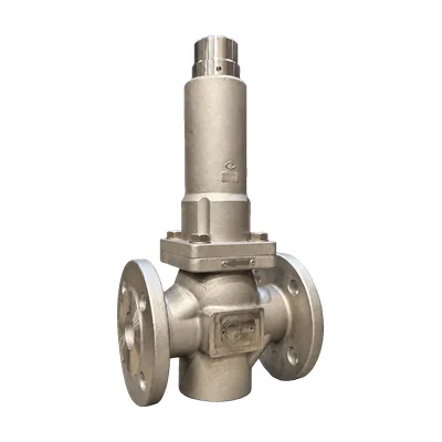

Pressure relief in mining slurry lines: abrasion resistance that lasts
Article contents
Why conventional pressure relief valves fail in mining slurry service
Mining slurry pipelines are some of the most demanding hydraulic environments on earth. A copper concentrate line moving 30% solids at 3 m/s, a tailings discharge running 24/7 across kilometers of pipe, or a mill circuit recirculating high-density slurry under fluctuating loads all share one trait: every pressure component in the line is fighting abrasion every second it operates.
Pressure relief valves are no exception. A relief valve that performed flawlessly on clean water can lose its sealing capability in weeks when exposed to abrasive solids—sometimes in days.
Before specifying a slurry relief valve for a mining operation in the U.S. or Canada, it is worth understanding why conventional designs fail, where these valves are typically installed on a mining circuit, and which failure modes engineers encounter most often in the field.
What makes slurry different from clean water: solids loading, particle size, and erosive velocity
Slurry is not water with a few suspended particles. In a typical copper concentrate pipeline, the fluid is 50–65% solids by weight, carrying particles ranging from a few microns up to 5–10 mm depending on the milling stage. In tailings service, solids loading often climbs above 70% in thickened or paste applications.
The combination of high solids concentration, particle hardness (copper sulfide ores routinely register 5–6 on the Mohs scale, iron ores 6–7), and continuous flow creates a fundamentally different wear environment than any clean-fluid service.
The single most influential variable is erosive velocity. Below approximately 2 m/s, particles tend to settle out, blocking lines and causing operational problems. Above 5 m/s, particles impinge directly on every flow obstruction—including the seat and disc of any relief valve along the line—accelerating wear exponentially.
The window of acceptable velocity, typically 2.5–4 m/s in long-distance slurry lines, leaves no margin for components that aren't engineered specifically for abrasive duty.
Where relief valves are installed on a mining slurry circuit: pumps, surge tanks, and tailings transport lines
Relief valves appear at several critical points in a mining slurry system. The most common is immediately downstream of high-pressure slurry pumps—centrifugal stages handling concentrate to the flotation cells, or positive-displacement pumps moving thickened tailings to the dam.
A pump shutdown, an electrical trip, or a downstream valve closure can spike line pressure dangerously fast; without a properly sized relief valve, that spike propagates through every pipe joint and elbow until it finds the weakest fitting.
A second installation point is on surge tanks and air-charged accumulators, used to dampen pulsations in long pipelines. Here, the relief valve serves as the secondary protection if the surge tank itself loses its air charge. A third point is on process equipment: cyclone underflows, thickener feed lines, and concentrate dewatering circuits, where overpressure events can damage sensitive equipment. Each location demands a relief valve sized and built specifically for the local flow, solids content, and service conditions.
The three failure modes engineers see most often: seat erosion, trim grooving, and disc impingement
Three failure modes account for the majority of slurry relief valve replacements. The first is seat erosion: every time the valve cracks open and recloses, abrasive particles pass between the disc and seat at high velocity. Within a few thousand cycles, the seating surface develops radial grooves that prevent tight shutoff, causing continuous leakage of slurry to the discharge line. On a tailings pipeline, that leak can release several cubic meters of slurry per day before it is even detected.
The second failure mode is trim grooving along the body internals. The flow path through a relief valve includes geometric transitions—nozzle to chamber, chamber to outlet—where slurry decelerates and changes direction. Particles concentrate along the outer wall of every bend, eroding shallow grooves that eventually compromise the wall thickness. The third mode is disc impingement in valves that don't return cleanly to the closed position. Each partial reseating allows slurry to wash across the disc face, removing material from the impact zone until the valve no longer closes reliably.
How an abrasion-resistant relief valve is engineered for mining service
A relief valve built for mining slurry service starts from a different blueprint than one designed for clean fluids. Material selection, internal geometry, and replacement-parts strategy are all reconsidered with abrasion as the primary constraint, not a secondary concern. The result is a valve that costs more up front but delivers tenfold service life in tailings and concentrate applications, with predictable maintenance intervals instead of unscheduled shutdowns.
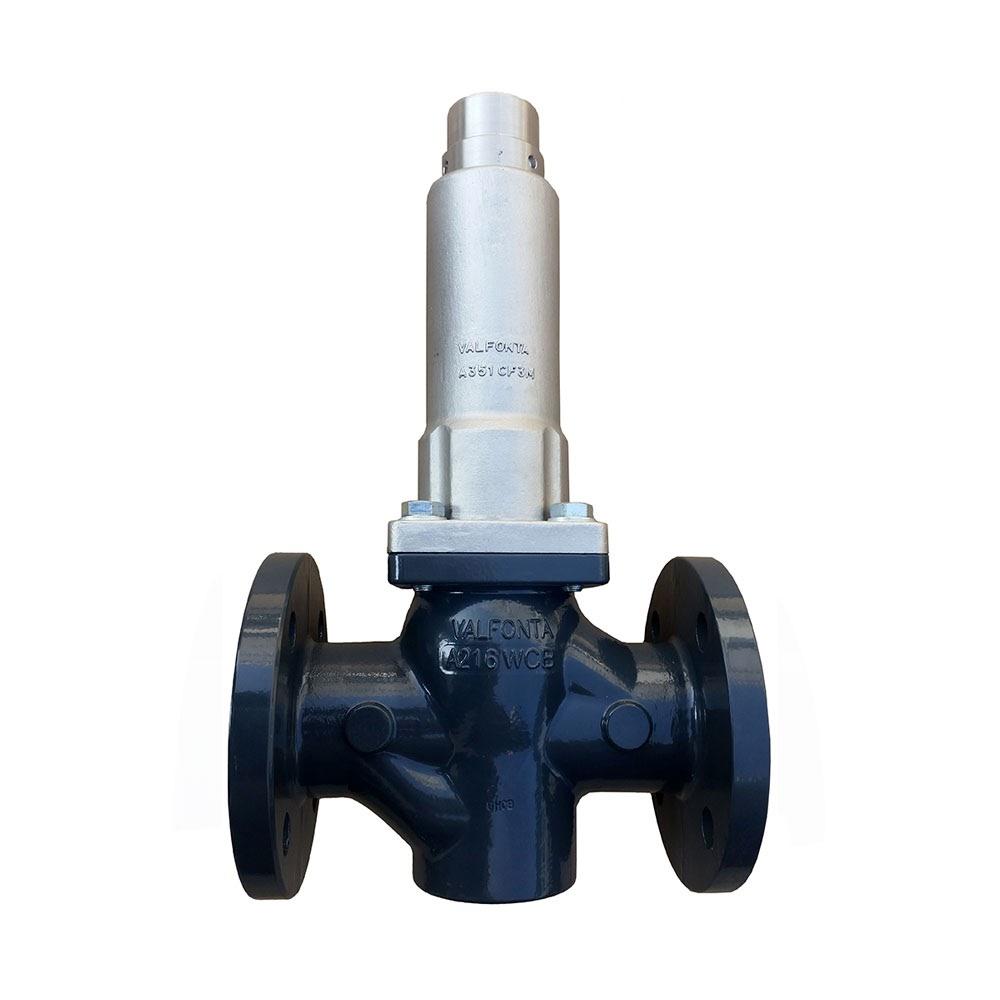
Valfonta's PRV and S series of pressure relief valves are engineered with this philosophy in mind, with configuration options specifically aimed at abrasive-fluid applications in mining and mineral processing.
Material selection: AISI 316L base, hardened trims, Stellite overlays, and ceramic inserts
For mining slurry service, the body of a relief valve is typically supplied in AISI 316L stainless steel, which combines corrosion resistance against the chemicals used in flotation and reagent injection with reasonable mechanical strength. For more aggressive duty, CF3M cast stainless (the casting equivalent of 316L) or duplex stainless steels (2205, 2507) are specified to handle chloride-rich tailings water without pitting.
The real abrasion resistance lives in the trim: the moving components in contact with the high-velocity slurry. Standard 316L trims fail quickly in slurry; high-performance configurations use 17-4PH precipitation-hardened stainless (up to Rockwell C44 hardness), Stellite 6 overlays on seating surfaces (Rockwell C40–48, retaining hardness at elevated temperatures), or tungsten carbide inserts for the highest-velocity applications.
In some installations, alumina or silicon carbide ceramic inserts are bonded into the flow path to provide near-glass abrasion resistance, although at the cost of brittle behavior under impact loading.
Geometry matters: full-bore flow paths, low-impingement seat angles, and replaceable wear sleeves
Material selection alone is not enough. The internal geometry of the valve has to be engineered to minimize the energy that slurry transfers to wear surfaces. Full-bore flow paths with no sudden contractions reduce velocity peaks where particles impact the body wall.
Low-impingement seat angles—typically less than 30° rather than the 45° standard of clean-fluid valves—deflect particles tangentially across the seat rather than driving them perpendicular to the sealing surface.
Beyond geometry, the most important design feature for mining service is the replaceable wear sleeve. A wear sleeve is a sacrificial liner installed in the chamber that absorbs the bulk of the abrasive impact. When the sleeve reaches end of life, a maintenance technician replaces only the sleeve—not the entire valve—reducing downtime from days to hours and cutting lifecycle cost by a factor of three or four. This is the single most cost-effective design choice in slurry relief valves and a feature procurement teams should always specify on a North American mine site.
How Valfonta configures its PRV and S-series for mining slurry duty
Valfonta's pressure relief valves are manufactured at the company's facility in Badalona, Spain, with more than 60 years of in-house engineering applied to each unit. For mining slurry applications, the PRV53, PRV54, and PRV55 models are configured as excess-pressure valves with AISI 316L bodies, hardened 17-4PH trims, and optional Stellite overlay on the seat. The S1, S2, and S3 relief valves are offered with the same materials options and add replaceable wear sleeves in the body chamber on request.
All valves are supplied with ANSI B16.5 raised-face flanges (Class 150 or Class 300) for direct integration into North American piping standards, and Valfonta provides EN 10204 3.1 material certificates along with the corresponding ASTM cross-references (ASTM A276/A479 for 316L bar stock, A182 for forgings, A351 CF3M for castings) accepted by U.S. and Canadian inspection authorities. NACE MR0175 / MR0103 compliance is available on request for projects where mining service overlaps with sour-gas environments.
Specifying and maintaining slurry relief valves on a North American mine site
Specifying a slurry relief valve correctly is half the job; maintaining it predictably is the other half. North American mine sites operate at scale, often in remote locations where unscheduled maintenance is expensive and inventory of specialty parts is limited.
A clear specification, a realistic sizing approach, and a disciplined inspection program reduce the risk of unexpected failures and let the procurement team plan parts and labor with confidence. The recommendations below summarize how Valfonta's technical team works with U.S. and Canadian mining clients to specify, install, and maintain abrasion-resistant relief valves.
Sizing for surge events versus continuous overpressure: two very different calculations
Mining slurry systems experience two distinct overpressure scenarios, and a relief valve must be sized for the more demanding of the two. Continuous overpressure results from a slow process drift—pump speed increase, downstream valve restriction, line plugging—and produces a manageable rise in line pressure that the relief valve must vent at low to moderate flow rates.
Sizing here follows standard ASME B16.34 and API 520 methodology, with the relief valve set 10–15% above maximum operating pressure and sized to discharge the worst-case continuous flow.
Surge events are different. A pump trip, a sudden downstream valve closure, or a column separation event can create a pressure wave that propagates through the line at the speed of sound in slurry (typically 800–1,200 m/s) and peaks in milliseconds.
Sizing for surge requires transient hydraulic analysis (using software such as KYPIPE or AFT Impulse) and often calls for relief valves with significantly larger discharge capacity than continuous sizing would suggest. On critical pipelines, dual-stage relief schemes—a small valve for continuous overpressure and a large surge relief valve—are often the most reliable approach.
Inspection intervals, wear monitoring, and a realistic parts-replacement strategy
A realistic maintenance interval for slurry relief valves depends heavily on solids loading, particle hardness, and the frequency of relief events. As a starting reference, Valfonta recommends quarterly visual inspection with seat-lift verification, annual bench testing to confirm set pressure and reseating performance, and wear-sleeve replacement every 12–24 months based on inspection results. In high-wear service (high-iron tailings, abrasive concentrates), more frequent intervals may be needed; in less aggressive duty (cleaner mill water lines), intervals can be extended.
Predictive maintenance using acoustic emission sensors or ultrasonic thickness measurements at known wear points helps refine the schedule without unnecessary downtime. Valfonta supplies original spare parts (wear sleeves, seats, springs, trim assemblies) with documented traceability for every order, allowing maintenance teams to maintain a small stock of consumables on site and complete a full overhaul without removing the valve from service in many cases.
Specifying a relief valve for an abrasive-fluid mining application demands experience that goes well beyond standard valve catalogs. Valfonta's engineering team has been designing pressure protection equipment since 1962 and supports North American mining operations directly from Badalona, Spain. Request a technical consultation through the contact form and receive a sized, material-specified proposal built around your slurry data and your project schedule.
Frequently asked questions about slurry relief valves in mining
What is the typical service life of a slurry relief valve in a copper concentrate pipeline?
With AISI 316L body, 17-4PH hardened trim, and a replaceable wear sleeve, a properly sized Valfonta PRV or S-series valve in a typical copper concentrate pipeline (50–60% solids, 3 m/s, moderate cycling) achieves 3–5 years between major overhauls and 12–24 months between wear-sleeve replacements. Service life drops significantly in higher-velocity or higher-solids applications; Valfonta's technical team provides expected-life estimates based on the specific slurry data the client submits.
Can a standard stainless steel relief valve handle 50% solids slurry, or do I need a hardened trim?
A standard AISI 316L trim will function in 50% solids slurry but will typically last only 2–6 months before seat erosion compromises shutoff. For any slurry service above approximately 30% solids loading, Valfonta recommends specifying a hardened trim (17-4PH minimum, Stellite overlay preferred) and a replaceable wear sleeve. The incremental cost is small relative to the maintenance savings and reduced downtime over the valve's service life.
How is a slurry relief valve sized differently from a clean-fluid relief valve?
Slurry relief valves are sized for both continuous overpressure (ASME B16.34 / API 520 methodology, adjusted for two-phase flow density) and surge transients (computed using transient hydraulic modeling).
Standard sizing software designed for clean fluids underestimates the required discharge area in slurry service because it does not account for compressibility effects of entrained air or for the higher effective density of the discharged mixture. Valfonta's engineering team applies sector-specific correlations validated on mining and tailings projects.
Does Valfonta offer ASTM-certified materials and NACE compliance for North American mining specs?
Yes. All Valfonta stainless steel components carry EN 10204 3.1 certificates with explicit ASTM cross-references (A276, A479, A182, A351 CF3M), accepted by U.S. and Canadian inspection bodies. NACE MR0175 and NACE MR0103 compliance for sour service is available on request, along with PMI (positive material identification) reports and hydrostatic test certificates per ASME B16.34. Documentation is supplied in English and follows U.S. project documentation conventions.
What inspection interval is realistic for a relief valve on a tailings line?
For a continuously operating tailings pipeline, Valfonta recommends quarterly visual inspection of the external valve and discharge line, semi-annual seat-lift testing to confirm the valve cycles cleanly, and annual full bench testing to validate set pressure and reseating. Wear sleeves should be replaced on a condition-based schedule informed by inspection findings, typically every 12–18 months in moderate-wear service. These intervals are guidelines and should be adjusted based on specific slurry conditions.
How do I get a slurry relief valve quoted and shipped to a remote mine site in the U.S. or Canada?
Valfonta works directly with North American engineering firms, EPC contractors, and mining end users. Quotes are issued based on a completed slurry data sheet (solids loading, particle size distribution, velocity, pressure rating, chemistry, and surge analysis if available).
Lead times for standard configurations are typically 4–8 weeks from order, with expedited options available for critical projects. Shipping to North American ports is handled through established freight forwarders, with documentation prepared for U.S. and Canadian customs clearance.
Related valves
Related articles


Can we help with your installation?
Tell us the fluid, the inlet and outlet pressures, the temperature, and the flow rate, and we will recommend the right valve.
You can also call 933 720 888 or email valfonta@valfonta.com.