


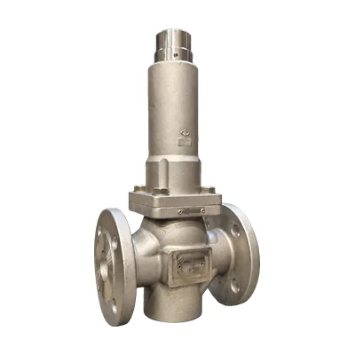

Pressure reducing valve · Bellows-balanced
M2F bellows pressure reducing valve
No water seal pot
Self-operated reducing valve balanced by an AISI 316Ti stainless steel bellows, which maintains the outlet pressure even when the inlet pressure fluctuates. It works with steam up to 200 °C without a condensate pot, and also with compressed air, gases, and liquids, from DN15 to DN50.
- SizesDN15 to DN50
- Pressure ratingPN25 to PN40 · Class 150/300
- Inlet pressureup to 25 barg
- Outlet pressure1 to 10 barg in two ranges
- Temperatureup to 200 °C with steam
- Kv3.5 to 32 m³/h
Questions about sizing? Call 933 720 888 or email valfonta@valfonta.com.
- In-house design and manufacturing in Badalona
- ATEX II 2 GD marking for zones 1 and 21
- Steam up to 200 °C without a condensate pot
- Recommended spare parts marked in the exploded view
What the M2F is used for
The M2F is the bellows version of the M2 pressure reducing valve. Instead of a diaphragm, an AISI 316Ti stainless steel bellows receives the outlet pressure and opposes the adjusting spring, with no auxiliary power. The valve closes when the outlet pressure rises.
Its main difference is that it does not need a condensate pot: it works with steam up to 200 °C connected directly. It is supplied with internal pressure sensing, and external sensing is optional.
- SteamSteam pressure reduction up to 200 °C, with no water seal pot.
- Chemical laboratoriesStable pressure in laboratory installations.
- Water networksWater distribution and wastewater installations.
- Compressed airReducing line pressure to the working value.
- Fire protectionFire protection networks and sprinklers.
- Inert gas and fuel oilInert gas protection and fuel oil lines.
M2F technical specifications
| Type | Self-operated, direct-acting, bellows-balanced pressure reducing valve |
|---|---|
| Sizes | DN15 to DN50 |
| Connections | EN PN16 to PN40 flanges · ANSI 150/300 flanges · BSP or NPT thread · BW and SW ends: on request |
| Pressure rating | PN25 or PN40 depending on material · Class 150 or 300 |
| Maximum inlet pressure | 25 barg |
| Maximum differential pressure | 25 bar (DN15 to DN25) · 16 bar (DN40 to DN50) |
| Outlet pressure ranges | 1 – 4 barg · 3 – 10 barg · special ranges on request |
| Kv coefficient | 3.5 to 32 m³/h depending on DN |
| Maximum temperature | Steam: 200 °C · Air and nitrogen: 150 °C · Other gases: 80 °C |
| Plug | Graphite-filled PTFE as standard (200 °C). On request: PEEK (200 °C), EPDM or FKM (150 °C), NBR (80 °C) |
| Fluids | Steam, compressed air, gases, and liquids |
| Materials | Body in RG10 bronze (PN25), A216 WCB carbon steel or A351 CF3M stainless (PN40). Internals in AISI 316L stainless. Bellows in AISI 316Ti |
| Condensate tank | Not required |
| Pressure sensing point | Internal as standard. External with 10 × 1 mm tubing, optional on request |
| Mounting position | Horizontal pipe, following the arrow on the body |
| Pressure Equipment Directive | PED 2014/68/EU: the nameplate indicates whether CE marking is required |
| ATEX | II 2 GD c IIC Tx / c IIIC TxºC · certificate LOM 14.034 U |
Dimensions and weight
| DN15 | DN20 | DN25 | DN32 | DN40 | DN50 | |
|---|---|---|---|---|---|---|
| Kv (m³/h) | 3,5 | 5 | 9 | 13,5 | 22 | 32 |
| Length A (EN PN40, mm) | 130 | 150 | 160 | 180 | 200 | 230 |
| Length A (ANSI 150, in.) | ○ | ○ | 7,25″ | – | 8,75″ | 10″ |
| Length A (ANSI 300, in.) | ○ | ○ | 7,76″ | – | 9,25″ | 10,5″ |
| Height H (mm) | 340 | 340 | 350 | 350 | 365 | 365 |
| Approximate weight (kg) | 11 | 12 | 14 | 15 | 18 | 22 |
○: on request. Cap diameter (D): 140 mm on all sizes.
Exploded view and materials (29 parts)
| No. | Part | Material |
|---|---|---|
| 1 | Body | RG10, 1.0619 (WCB), or 1.4408 (CF3M) |
| 2 | Seat | 1.4404 (316L) |
| 3 | Stem | 1.4404 (316L) |
| 3b | Bushing guide | 1.4404 (316L) |
| 4 | Screw | Galvanized steel 8.8 (A2-70 with CF3M body) |
| 5 | Gasket (spare part) | PTFE |
| 6 | Nut (spare part) | AISI 316L stainless |
| 6b | Spring washer | Galvanized steel (A2-70 with CF3M body) |
| 7 | Nut | A2-70 stainless |
| 9 | Gasket | Graphite |
| 10 | Pusher | 1.4404 (316L) |
| 11 | Cap | Steel 1.1192, epoxy-coated (316L on request) |
| 12 | Spring guide | Galvanized steel 1.1191 (316L on request) |
| 14 | Adjusting screw | Galvanized steel 8.8 |
| 15 | Adjusting nut | Galvanized steel 8.8 |
| 16 | Adjusting spring | Steel 52SiCrNi5 (epoxy) |
| 18 | Stem | 1.4404 (316L) |
| 19 | Bellows (spare part) | AISI 316Ti stainless |
| 20 | M8 screw | Galvanized steel 8.8 (A2-70 with CF3M body) |
| 21 | Bellows support | Steel 1.1191, epoxy-coated (316L with CF3M body) |
| 23 | Spring support | AISI 302 stainless |
| 24 | Cover | Galvanized steel 1.1141 (316L on request) |
| 25 | Gasket | Graphite |
| 26 | Compensation gasket (spare part) | Graphite-filled PTFE with stainless spring (NBR, EPDM, Viton on request) |
| 27 | Guide stem | 1.4404 (316L) |
| 28 | Seat (spare part) | Graphite-filled PTFE (NBR, EPDM, Viton on request) |
| 29 | Seat screw | A2-70 stainless |
| 30 | Seat guide | 1.4404 (316L) |
| 31 | Seat holder | 1.4404 (316L) |
How the M2F works
Direct-acting: balance between the adjusting spring and the outlet pressure on the bellows.
- Closing by inlet pressure. The fluid flows in the direction of the arrow, and the stem–piston–gasket assembly tends to close the valve.
- Opening by the spring. Turning the adjusting screw clockwise compresses the spring, which acts on the bellows and the seat and opens the passage until the required outlet pressure is reached.
- Compensation. The compensation gasket and the bellows absorb inlet pressure variations.
- Closing as the outlet pressure rises. If the downstream pressure increases, the valve closes.
The M2F is not a safety valve: if necessary, install overpressure protection. More on this design in bellows-sealed valves.
M2F installation
Recommended layout: bypass, shutoff valves, strainer, pressure gauges, and safety valve. With steam, the M2F does not need a water seal pot, and internal pressure sensing eliminates the control line. More detail in how to install a pressure reducing valve and in our guide to reducing valves for steam.
- Shutoff valves (1, 1a) and bypass valve (1b)
- Strainer
- Inlet pressure gauge
- M2F reducing valve
- Safety valve
- Outlet pressure gauge
Installation and start-up
- Clean the pipe and install a strainer at the inlet, with room to remove and clean it.
- Install the valve in a horizontal pipe, with the flow in the direction of the arrow on the body.
- Support the pipe close to the flanges, never the valve or the actuator.
- If you ordered external pressure sensing, connect it with 10 × 1 mm tubing in the reduced-pressure zone, at least 1 m from the outlet, or to the manifold if there is one. If the valve oscillates, add a needle valve.
- Do not install a condensate pot: the bellows works with steam up to 200 °C connected directly.
- Connect the bypass beyond the pressure sensing point and open the shutoff valves slowly to avoid water hammer.
- Adjust the outlet pressure with the adjusting screw: compressing the spring (clockwise) raises it; releasing it (counterclockwise) lowers it.
Installation must be carried out by specialized personnel. In ATEX zones, ensure electrical conductivity between the valve and the installation. If the pressure is unstable, review the most common problems with reducing valves.
M2F technical documentation
Order and ATEX documentation: see our quality certificates.
M2F vs. other Valfonta reducing valves
Check whether the M2F is the right model or whether another reducing valve in the range suits you better.
Temperature in parentheses: with EPDM or Viton gaskets. Data from the Valfonta general reducing valve catalog (2025); the M2F is not listed in it, and its data come from its datasheet.
Frequently asked questions about the M2F
Does the M2F need a condensate pot?
No. Thanks to its stainless steel bellows, it works with steam up to 200 °C connected directly, with no water seal pot.
What is the difference between the M2F and the M2?
The M2 uses a diaphragm: it goes up to DN100, regulates from 0.02 barg, accepts 40 barg inlet pressure up to DN50, and, with steam, needs a water seal pot (up to 180 °C). The M2F uses a bellows: from DN15 to DN50, 25 barg inlet pressure, outlet pressure from 1 to 10 barg, and steam up to 200 °C with no water seal pot.
What outlet pressure can be set?
There are two standard ranges, 1 to 4 barg and 3 to 10 barg; other ranges on request. See how to adjust a reducing valve.
What temperature does it withstand?
Up to 200 °C with steam, 150 °C with air and nitrogen, and 80 °C with other gases, with a graphite-filled PTFE or PEEK plug. With an EPDM or FKM plug, the limit is 150 °C, and with NBR, 80 °C.
What spare parts does the manufacturer recommend?
The gasket (5), the nut (6), the bellows (19), the compensation gasket (26), and the seat (28). Maintenance is carried out with the valve installed, depressurized, and isolated.
Can it be installed in an ATEX zone?
Yes. It carries ATEX II 2 GD marking (certificate LOM 14.034 U) for zones 1, 2, 21, and 22, depending on the temperature class of the fluid. More in ATEX valves.
Other pressure reducing valve models
 M2 diaphragm reducing valveDN15–100 and outlet pressures from 0.02 barg.
 M1 reducing valveUp to DN150 and steam at 220 °C.
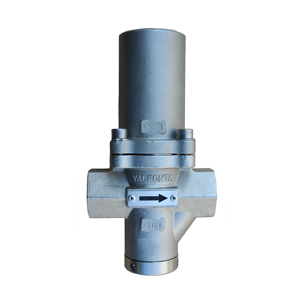 PRV44 reducing valveDN15–25, steam up to 210 °C.
 PRV45 reducing valveOutlet pressures from 0.01 barg; suitable for steam.
 VD reducing valveDN15–100, 40 bar, and steam up to 200 °C.
 PRV30 reducing valve316L stainless, DN15–25.
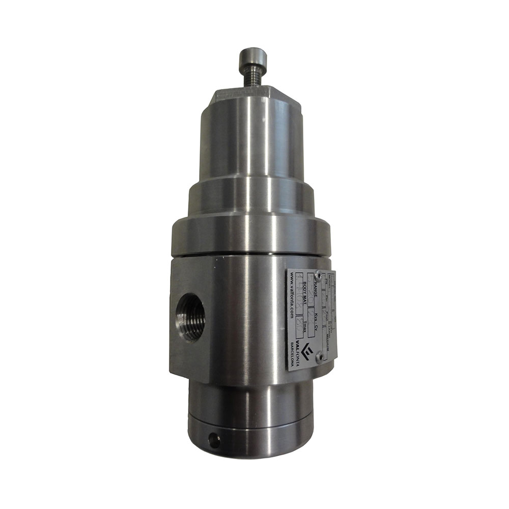 PRV20 reducing valve316L stainless, DN8–20 and 40 bar.
Request a quote for the M2F
Give us your installation details and we will recommend the right size, spring range, and plug.
- Fluid and operating temperature
- Inlet pressure and desired outlet pressure
- Maximum and minimum flow rate
- Size, connection, and body material
You can also call 933 720 888.