

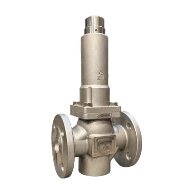

Pressure reducing valve · 3-point guided piston
VD pressure reducing valve
New: steam up to 200 °C
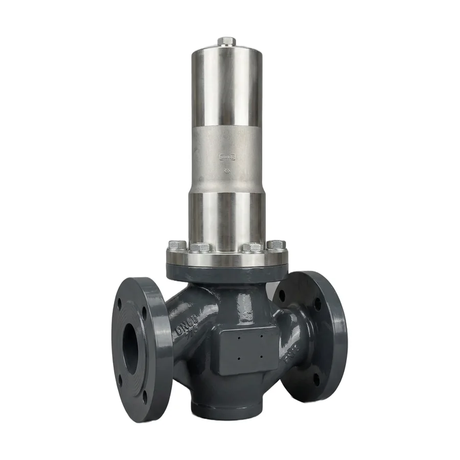
Self-regulating, direct-acting, single-seat reducing valve with a regulating piston guided at 3 points. It keeps the outlet pressure constant on steam up to 200 °C, liquids, compressed air, and inert gases, from DN15 to DN100 and with up to 40 barg inlet pressure. New: the VD is now available for steam up to 200 °C.
- SizesDN15 to DN100
- Pressure ratingPN16 to PN40 ANSI 150 and 300
- Inlet pressureup to 40 barg
- Outlet pressure1.5 to 16 barg standard 1.5 to 8
- Temperature−20 to 200 °C with AFLAS gaskets
- Kv3.5 to 115 m³/h
Questions about sizing? Call 933 720 888 or email valfonta@valfonta.com.
- In-house design and manufacturing in Badalona
- ATEX II 2 GD marking for zones 1 and 21
- High-hardness baked epoxy paint
- Genuine spare parts available
What the VD is used for
The VD is Valfonta's piston pressure reducing valve for medium and large sizes: it ranges from DN15 to DN100, with EN or ANSI flanges or threads up to 2″. It operates by direct action, with no auxiliary power, and absorbs inlet pressure variations thanks to an internal compensation hole in the stem.
The body is made of bronze, carbon steel, or stainless steel, with stainless steel internals, and is protected with baked epoxy paint. It is very easy to adjust, and its internal design ensures efficient fluid flow. Its uses include water distribution networks and fire protection installations.
- Steam networksNew: steam pressure reduction up to 200 °C, from DN15 to DN100.
- Water distribution networksPressure reduction and stabilization in the network.
- Fire protection and sprinklersPressure regulation in sprinkler systems.
- WastewaterWastewater installations.
- Industrial compressed airReduction of network pressure for points of use.
- Fuel oilLiquid fuel supply lines.
- Laboratories and sanitary installationsChemical laboratory and sanitary installations.
VD technical specifications
| Type | Self-regulating, direct-acting, single-seat pressure reducing valve with a piston guided at 3 points |
|---|---|
| Sizes | DN15, 20, 25, 32, 40, 50, 65, 80, and 100 |
| Connections | DIN PN16, PN25, and PN40 flanges · ANSI Class 150 and 300 flanges · BSP or NPT female thread up to 2″ |
| Pressure rating | PN16 – PN25 – PN40 or Class 150 – Class 300 |
| Maximum inlet pressure | 40 barg |
| Maximum differential pressure (Δp) | 25 bar (DN15 to DN50) · 20 bar (DN65 and DN80) · 16 bar (DN100) |
| Outlet pressure range | 1.5 to 16 barg (standard, 1.5 to 8 barg) |
| Kv coefficient | From 3.5 m³/h (DN15) to 115 m³/h (DN100) |
| Temperature | −20 to +200 °C (with AFLAS gaskets) |
| Fluids | Steam (up to 200 °C), liquids, compressed air, and inert gases |
| Body material | RG10 bronze, WCB carbon steel, or CF3M stainless steel |
| Internals | 316L stainless steel (1.4404); bronze optional |
| Finish | High-hardness baked epoxy paint |
| Mounting position | Recommended in a horizontal pipe; some positions are permitted and one is not recommended |
| Pressure Equipment Directive | PED 2014/68/EU: depending on size and pressure, with or without CE marking (shown on the nameplate) |
| ATEX | II 2 GD c IIC Tx / c IIIC TxºC · certificate LOM 14.034 U |
Dimensions, weight, and Kv
| DN15 | DN20 | DN25 | DN32 | DN40 | DN50 | DN65 | DN80 | DN100 | |
|---|---|---|---|---|---|---|---|---|---|
| Kv (m³/h) | 3,5 | 5 | 9 | 13,5 | 22 | 32 | 57 | 82 | 115 |
| Cv (gpm) | 4 | 5,8 | 10,4 | 15,6 | 25 | 37 | 66 | 95 | 134 |
| Length A, DIN flanges | 130 | 150 | 160 | 180 | 200 | 230 | 290 | 310 | 350 |
| Length A, ANSI 150 | – | – | 184 | – | 222 | 254 | 276 | 298,5 | 352,5 |
| Length A, ANSI 300 | – | – | 197 | – | 235 | 267 | 292 | 317,5 | – |
| BSP / NPT thread | ½″ | ¾″ | 1″ | 1¼″ | 1½″ | 2″ | – | – | – |
| Dimension L | 240 | 240 | 250 | 250 | 300 | 300 | 415 | 430 | 490 |
| Weight (kg) | 10 | 10 | 12 | 13 | 16 | 18 | 35 | 50 | 60 |
Dimensions in millimeters. The dimensioned drawings are in the PDF datasheet.
Possible faults and solutions
| Symptom | Possible cause | Recommended solution |
|---|---|---|
| Pressure exceeds the setting | Worn seat and plug | Replace the worn components |
| Pressure drops below the setting | Valve installed backward; Kv too small; plug jammed | Check the arrow on the body and the sizing; replace the damaged parts |
| Erratic control | Particles between the seat and the plug | Remove the particles and replace the damaged parts |
| Fluctuating inlet pressure | Valve too large | Choose a lower Kv if necessary |
| Loud noise | High flow velocity; cavitation | Check the sizing; for gases, install a flow diffuser |
Exploded view and materials (33 parts)
| No. | Part | Material |
|---|---|---|
| 1 | Body | RG10 bronze, WCB carbon steel, or stainless steel CF3M |
| 2 | Seat | 1.4404 (316L) |
| 3 | Stem (DN65 to DN100) | 1.4404 (316L) |
| 4 | Washer | Stainless steel A2-70 |
| 5 | Screws | Stainless steel A2-70 |
| 6 | Piston | 1.4404 (316L) |
| 7 | Plunger | NBR |
| 8 | Safety O-ring | NBR |
| 9 | Cap cover | Stainless steel CF3M |
| 10 | Spring | Spring steel with epoxy paint (60–100 microns) |
| 11 | Adjusting nut | Galvanized steel 1.1191 |
| 12 | Plain bearing | PTFE + graphite |
| 13 | Adjusting stem | 1.4404 (316L) |
| 14 | Lock washer | Stainless steel A2-70 |
| 15 | O-ring | NBR |
| 16 | Piston stem | 1.4404 (316L) |
| 17 | Nut | Stainless steel A2-70 |
| 18 | O-ring | NBR |
| 19 | Plunger guide | 1.4404 (316L) |
| 20 | O-ring | NBR |
| 21 | Flat gasket | PTFE |
| 22 | O-ring | NBR |
| 26 | Balancing plunger | NBR or PTFE + graphite + 302 stainless |
| 27 | Lower bushing guide | 1.4404 (316L) |
| 28 | Plug | NBR or graphite-filled PTFE |
| 29 | Plug screw | Stainless steel A2-70 |
| 30 | Plug guide (DN65 to DN100) | 1.4404 (316L) |
| 31 | Plug holder | 1.4404 (316L) |
| 41 | Lower bushing stem (DN100) | Stainless steel AISI 316L |
| 42 | O-ring (DN100) | NBR |
| 43 | Spring washer (DN100) | Stainless steel AISI 316L |
| 44 | Screws (DN100) | Stainless steel A2-70 |
| 51 | Stem, replaces 3 and 30 (DN15 to DN50) | 1.4404 (316L) |
Recommended spare parts
| Reference | Description | Parts |
|---|---|---|
| VD.SP1 | Gaskets and seats | 7, 8, 18, 20, 21, 22, 26, and 28 (and 42 on DN100) |
| VD.SP2 | Spring | 10 |
How the VD works
The VD works by a balance of forces on the regulating piston. It needs no air, electricity, or external pressure sensing points.
- Closing by inlet pressure. The upstream pressure reaches the valve and pushes the piston upward, which closes the passage.
- Opening by the spring. With the valve closed, turning the adjusting screw (13) clockwise compresses the spring (10), which acts on the bushing and the seat and opens the valve.
- Regulation. The valve opens the passage until the set downstream pressure is reached.
- Compensation. Inlet pressure variations are absorbed by compensating the upper section of the bushing, which is connected through the internal hole in the stem (51).
VD installation
Valfonta recommends installing the VD with a bypass, as shown in this diagram, so that maintenance can be carried out without interrupting service. For more detail, see our guide on how to install a pressure reducing valve.
- Isolation valves (1, 1a) and bypass valve (1b)
- Strainer
- Inlet pressure gauge
- VD reducing valve
- Safety valve
- Outlet pressure gauge
Installation and start-up
- Clean the pipe before installing the valve, so that no impurities affect its operation.
- Install a strainer at the valve inlet to protect it.
- Install the valve in a horizontal pipe and follow the arrow on the body. There is one non-recommended position in which it might not work properly: check it in the manual.
- Support the pipe, not the valve: supports should be as close as possible to the reducing valve, but never attached to it or to the actuator.
- Start up slowly: open the shutoff valves gradually to avoid water hammer.
- Adjust the outlet pressure with the adjusting screw (13): turning it clockwise compresses the spring and raises the pressure; turning it counterclockwise lowers it.
For maintenance, fully loosen the adjusting nut to release the spring tension, and make sure there is no pressure in the pipe or the valve and that it is at ambient temperature. The seat is removed with a special tool, whose drawing you can request from Valfonta. If there is noise or the pressure is not maintained, see the troubleshooting table and our articles on reducing valve problems and cavitation in reducing valves.
VD technical documentation
Do you need an order certificate or the ATEX documentation? See our quality certificates or request it from our technical team.
VD vs. other Valfonta reducing valves
The VD is the largest-diameter piston reducing valve in the range. This table helps you check whether it is the right model or whether another one suits you better.
Temperature in parentheses: with EPDM or Viton gaskets. Data from the Valfonta general pressure reducing valve catalog (2025). If you are unsure whether to choose a piston or a diaphragm valve, read our comparison of piston and diaphragm reducing valves.
Frequently asked questions about the VD
Can the VD be used with steam?
Yes. It is new to the range: the VD is now available for steam up to 200 °C, with AFLAS gaskets. Tell us the steam pressure and temperature and we will confirm the configuration.
What outlet pressure can be set?
The outlet range is 1.5 to 16 barg; the standard range is 1.5 to 8 barg. The inlet pressure can reach 40 barg, with a maximum differential pressure of 25 bar up to DN50, 20 bar on DN65 and DN80, and 16 bar on DN100.
How do you adjust the outlet pressure?
With the adjusting screw (13). Turning it clockwise compresses the spring and raises the outlet pressure; turning it counterclockwise lowers it. We explain it in how to adjust a pressure reducing valve.
What maintenance does it need?
Very little. The gaskets, seat, stem, and plug undergo normal wear and are replaced when necessary; this can be done with the body installed, depressurized, and isolated. There are two spare part kits: gaskets and seats (VD.SP1) and spring (VD.SP2).
Can it be installed in an ATEX zone?
Yes. The VD carries ATEX II 2 GD marking (certificate LOM 14.034 U) and can be used in zones 1 and 2 (flammable gases, vapors, and liquids) and 21 and 22 (combustible dust), within the temperature class corresponding to the fluid temperature.
Other pressure reducing valve models
 PRV30 reducing valve316L stainless, from DN15 to DN25 and up to 25 bar.
 PRV20 reducing valve316L stainless, from ¼″ to ¾″ and up to 40 bar inlet.
 PRV44 reducing valveDN15–25, bellows-balanced, and for steam up to 210 °C.
 PRV45 reducing valveVery low outlet pressures, from 0.01 barg; suitable for steam.
 M1 reducing valveUp to DN150 and 220 °C, for steam.
 M2 diaphragm reducing valveDN15–100, outlet pressures from 0.02 barg, and steam up to 180 °C.
 M2 bellows reducing valveVersion with sealing bellows.
Request a quote for the VD
Give us your installation details and we will recommend the right size, body material, and gaskets.
- Fluid and operating temperature
- Inlet pressure and desired outlet pressure
- Maximum and minimum flow rate
- Body material and connection (DIN or ANSI flanges, or threaded)
You can also call 933 720 888.