


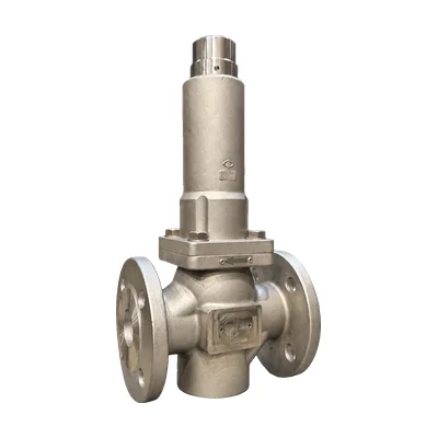

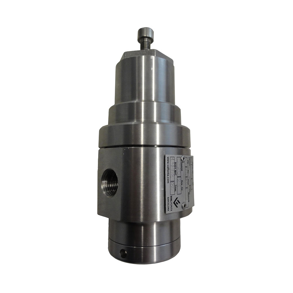
Pressure reducing valve · Self-operated by diaphragm
M1 pressure reducing valve
Steam up to 220 °C
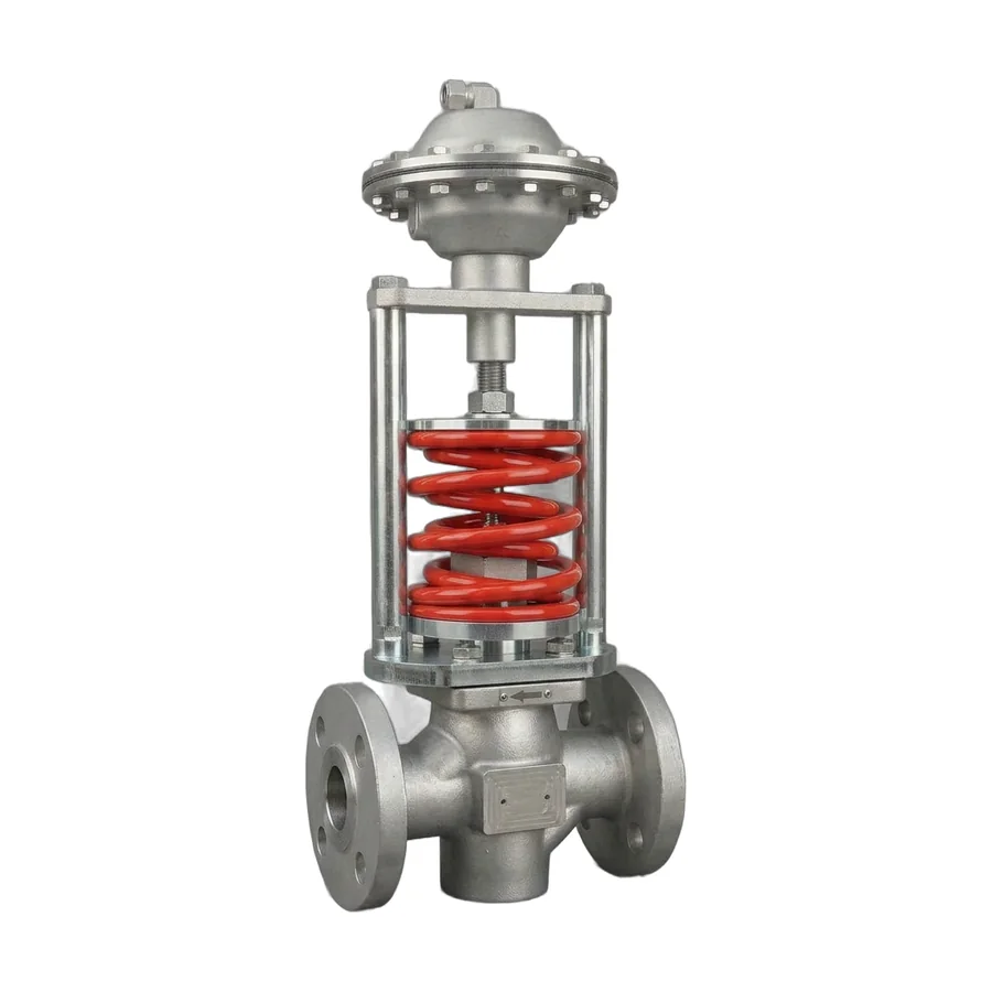
Self-operated, single-seat reducing valve: the diaphragm controls the outlet pressure and a double-layer stainless steel bellows seals the stem, with no auxiliary power. It works with steam, compressed air, inert gases, and liquids, from DN15 to DN150.
- SizesDN15 to DN150
- Pressure ratingPN16 to PN40 · Class 150/300
- Inlet pressureup to 40 barg 25 barg from DN65
- Outlet pressure0.1 to 15 barg
- Temperatureup to 220 °C with water seal pot
- Kv3.5 to 240 m³/h
Questions about sizing? Call 933 720 888 or email valfonta@valfonta.com.
- In-house design and manufacturing in Badalona
- ATEX II 2 GD marking for zones 1 and 21
- Bellows-sealed stem with anti-rotation system
- Genuine spare parts using the nameplate serial number
What the M1 is used for
The M1 is a self-operated pressure reducing valve: the outlet pressure reaches the diaphragm through a control line and is balanced against the adjusting springs. It needs no auxiliary power and responds quickly to changes in demand.
It is the model in the range that reaches the largest size, DN150, and the highest temperature, 220 °C with an EPDM+PTFE diaphragm and a condensate pot. From DN65 it incorporates a plunger that compensates for the inlet pressure.
- Steam networksSteam pressure reduction up to 220 °C, with a water seal pot.
- Compressed airAdjusting the network pressure to the value each point of use requires.
- Inert gasesNon-flammable gas lines.
- LiquidsWater and other liquids; above 125 °C, with a water seal pot.
- High flow ratesUp to DN150 and a Kv of 240 m³/h.
M1 technical specifications
| Type | Self-operated, single-seat globe reducing valve with diaphragm-compensated outlet pressure |
|---|---|
| Sizes | DN15 to DN150 |
| Connections | EN 1092 PN16 to PN40 flanges · ANSI 150/300 flanges · BSP or NPT thread (½″ to 2″) |
| Pressure rating | PN16, PN25, or PN40 · Class 150 or 300 |
| Maximum inlet pressure | 40 barg (DN15 to DN50) · 25 barg (DN65 to DN150) |
| Maximum differential pressure | 25 bar (DN15–50) · 20 bar (DN65–80) · 16 bar (DN100–150) |
| Outlet pressure ranges | 0.1–1.5 · 1–3 · 2–5 · 4–8 · 7–15 barg |
| Kv coefficient | 3.5 to 240 m³/h depending on size. Reduced Kv on request |
| Temperature at the actuator | EPDM diaphragm: −40 to 125 °C · EPDM+PTFE with condensate pot: up to 220 °C |
| Plug | Graphite-filled PTFE as standard (220 °C). Also NBR (80 °C), PEEK, EPDM… |
| Fluids | Steam, compressed air, inert gases, and liquids |
| Materials | Body in RG10 bronze, A216 WCB carbon steel, or A351 CF3M stainless. AISI 316L stainless internals. Double-layer AISI 316Ti bellows |
| Pressure sensing point | External control line, 10 × 1 mm tubing |
| Mounting position | Horizontal pipe, actuator facing down (facing up only with gases and liquids up to 80 °C) |
| Pressure Equipment Directive | PED 2014/68/EU: the nameplate indicates whether CE marking is required |
| ATEX | II 2 GD c IIC Tx / c IIIC TxºC · certificate LOM 14.034 U |
| On request | Monel or bronze internals · pressure sensing in the body (settings above 1 bar) · duplex or super duplex body · weld ends |
Dimensions and weight
| DN15 | DN20 | DN25 | DN32 | DN40 | DN50 | DN65 | DN80 | DN100 | DN125 | DN150 | |
|---|---|---|---|---|---|---|---|---|---|---|---|
| Kv (m³/h) | 3,5 | 5 | 9 | 13,5 | 22 | 32 | 57 | 82 | 115 | 190 | 240 |
| Length A (EN) | 130 | 150 | 160 | 180 | 200 | 230 | 290 | 310 | 350 | 400 | 480 |
| Length A (ANSI 150) | ○ | ○ | 184 | – | 222 | 254 | 276 | 298,5 | 352,5 | – | 451 |
| Length A (ANSI 300) | ○ | ○ | 197 | – | 235 | 267 | 292 | 317,5 | – | – | – |
| Height L | 440 | 445 | 450 | 455 | 463 | 475 | 560 | 560 | 575 | 600 | 640 |
| Weight (kg) | 20 | 22 | 24 | 28 | 32 | 35 | 52 | 57 | 68 | 85 | 105 |
Dimensions in millimeters. ○: on request. For DN150, 450 mm length on request.
Outlet ranges and actuator diameter (mm)
| Range (barg) | DN15–20 | DN25–32 | DN40–50 | DN65 | DN80 | DN100 | DN125 | DN150 |
|---|---|---|---|---|---|---|---|---|
| 0,1 – 1,5 | 295 | 295 | 295 | 295 | 350 | 350 | – | – |
| 1 – 3 | 255 | 255 | 255 | 255 | 295 | 295 | 295 | 350 |
| 2 – 5 | 230 | 230 | 230 | 230 | 255 | 255 | 255 | 295 |
| 4 – 8 | 195 | 195 | 195 | 195 | 230 | 230 | 230 | 255 |
| 7 – 15 | 175 | 175 | 175 | 175 | 195 | 195 | 195 | 230 |
Exploded view and materials (44 parts)
| No. | Part | Material |
|---|---|---|
| 1 | Body | RG10, 1.0619 (GS-C25N), or 1.4408 |
| 3 | Seat guide | 1.4404 (316L) |
| 4 | Bushing | 1.4404 (316L) |
| 5 | Bushing washer | 1.4404 (316L) |
| 6 | Cover | Steel 1.1191 or 1.4404 (316L) |
| 7 | Screws | Steel 8.8 or A2 stainless |
| 8 | Bellows guide | Steel 1.0570, 1.1191, or 316L |
| 9 | O-ring or gasket | Viton or graphite + SS304 |
| 10 | Springs | Steel 1.0904 (55Si7) |
| 11 | Bearing | Steel 1.3505 (100Cr6) |
| 12 | Upper spring support | Steel 1.1191 |
| 13 | Adjusting nut | Steel 8.8 |
| 14 | Plate | Steel 1.1191 |
| 15 | M12 nut | Steel 8.8 |
| 16 | Diaphragm stem guide | Steel 1.1191 |
| 17 | Nut | Steel 8.8 |
| 18 | Fitting | Brass or stainless |
| 19 | Diaphragm | EPDM, EPDM+PTFE, NBR, Viton… |
| 20 | Upper actuator | Steel sheet 1.0335 epoxy or 316 stainless |
| 21 | Diaphragm nut | 1.4301 (304) |
| 22 | O-ring | Viton |
| 23 | Diaphragm plate | Steel 1.1191 |
| 24 | Diaphragm stem | Steel 1.1191 |
| 25 | Screw | A2 stainless |
| 25b | Nut | A2 stainless |
| 26 | Lower actuator | Steel sheet 1.0335 epoxy or 316 stainless |
| 27 | Screw | Steel 8.8 |
| 28 | Anti-rotation system | Steel 1.1191 |
| 29 | Adjusting stem | 1.4301 (304) |
| 30 | Bearing guide | 1.4307 (304L) |
| 31 | Column | Steel 1.1191 |
| 32 | Bellows guide nut | Steel 1.1191 or 1.4404 (316L) |
| 33 | Bellows | AISI 316Ti stainless |
| 34 | Lower spring support | Steel 1.1191 |
| 35 | Body gasket | Graphite + SS304 |
| 35b | Guide gasket | Graphite + SS304 |
| 36 | Bushing guide | 1.4404 (316L) |
| 37 | Balancing collar | Graphite-filled PTFE |
| 38 | Allen screw | A2 stainless |
| 39 | Seat holder | 1.4404 (316L) |
| 40 | Plug seat | Graphite-filled PTFE |
| 41 | Washer | A2 stainless |
| 42 | Nut | 1.4404 (316L) |
| 45 | Seat bushing | 1.4404 (316L) |
How the M1 works
Balance of forces between the adjusting springs and the outlet pressure acting on the diaphragm: the valve closes when the downstream pressure rises.
- Fluid inlet. The fluid enters in the direction of the arrow and moves the plug, whose position sets the flow rate.
- Adjustment. The adjusting nut tensions the springs and sets the outlet pressure.
- Sensing at the diaphragm. The outlet pressure reaches the diaphragm through the control line and opposes the springs, moving the plug.
- Proportional closing. If the pressure exceeds the set value, the valve closes proportionally until the set value is restored.
- Compensation from DN65. A plunger balances the inlet pressure and absorbs its fluctuations.
Piston or diaphragm? See our comparison of piston and diaphragm reducing valves.
Video of the M1 model.
M1 installation
Recommended layout: bypass, shutoff valves, strainer, pressure gauges, and safety valve. In addition, the M1 needs a control line and, with steam or liquids above 125 °C, a condensate pot (water seal pot). More details in our guides on how to install a pressure reducing valve and on the pressure reducing valve for steam.
- Shutoff valves (1, 1a) and bypass valve (1b)
- Strainer
- Inlet pressure gauge
- M1 reducing valve
- Safety valve
- Outlet pressure gauge
Installation and start-up
- Clean the pipe and install a strainer upstream to protect the seat.
- Install the valve in a horizontal pipe, following the arrow on the body. If condensate is present, give the pipe a slight downward slope.
- Point the actuator downward, the standard position. Upward only with gases and liquids up to 80 °C; never horizontal.
- Support the pipe close to the flanges, never the valve or the actuator.
- Connect the control line (10 × 1 mm tubing) in the reduced-pressure zone, at least 1 m from the outlet, or to the manifold if there is one. If the valve oscillates, add a needle valve.
- With steam or above 125 °C, install the water seal pot at the highest point, connected from the side and with a slight slope toward the pipe. Fill it with water until it overflows and close the cap.
- Connect the bypass beyond the pressure sensing point and open the shutoff valves slowly to avoid water hammer.
- Adjust the outlet pressure with the adjusting nut: compressing the springs (clockwise) raises it; releasing them lowers it.
Installation must be carried out by specialized personnel. In ATEX zones, ensure electrical conductivity between the valve and the installation. If the pressure fluctuates, review the most common reducing valve problems.
M1 technical documentation
Order and ATEX documentation: see our quality certificates.
M1 vs. other Valfonta reducing valves
The M1 is the only reducing valve in the range that reaches DN150 and 220 °C. Check whether another model suits you better.
Temperature in parentheses: with EPDM or Viton gaskets. Data from the Valfonta general reducing valve catalog (2025).
Frequently asked questions about the M1
Can the M1 be used with steam?
Yes, up to 220 °C, with an EPDM+PTFE diaphragm and a condensate pot on the control line. With an EPDM diaphragm, the limit is 125 °C.
When is the condensate pot required?
With steam and with liquids above 125 °C. The water seal pot, filled with water, protects the diaphragm from overheating and always goes at the highest point of the line.
What outlet pressure can be set?
From 0.1 to 15 barg, in five ranges, each with its own actuator. The inlet accepts 40 barg up to DN50 and 25 barg from DN65. See how a reducing valve is adjusted.
What should I do if the pressure fluctuates at low flow rates?
If the pressure drop is very large, install two reducing valves in series. Also check that the control sensing point is at least 1 m away and, if the valve is too large, replace the 10 × 1 tubing with 6 × 4 tubing.
What maintenance does it need?
Periodically inspect gaskets and wear parts, with the valve installed, depressurized, and isolated. For spare parts, give the serial number on the nameplate.
Can it be installed in an ATEX zone?
Yes. It carries ATEX II 2 GD marking (certificate LOM 14.034 U) for zones 1, 2, 21, and 22, depending on the temperature class of the fluid. More in ATEX valves.
Other pressure reducing valve models
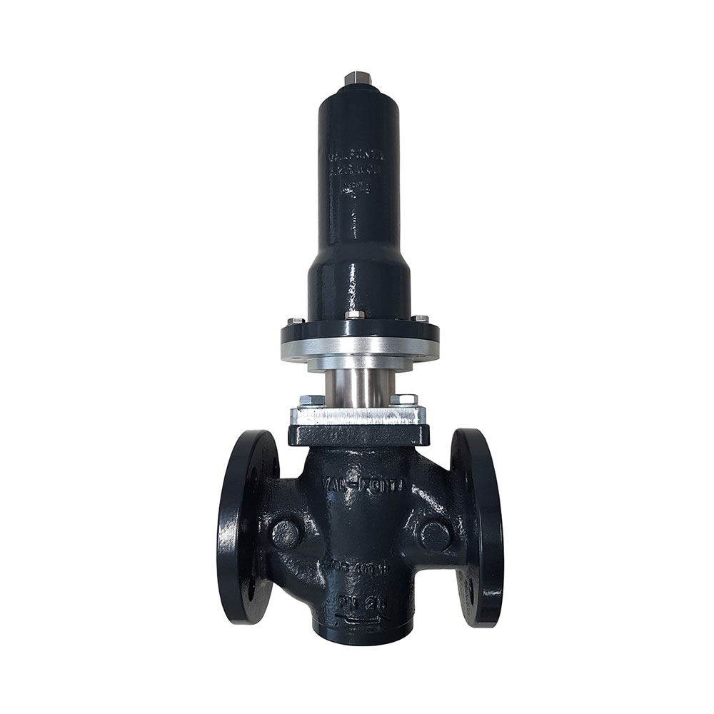 M2F bellows reducing valveDN15–50 and steam up to 200 °C without a water seal pot.
 M2 diaphragm reducing valveDN15–100 and outlet pressures from 0.02 barg.
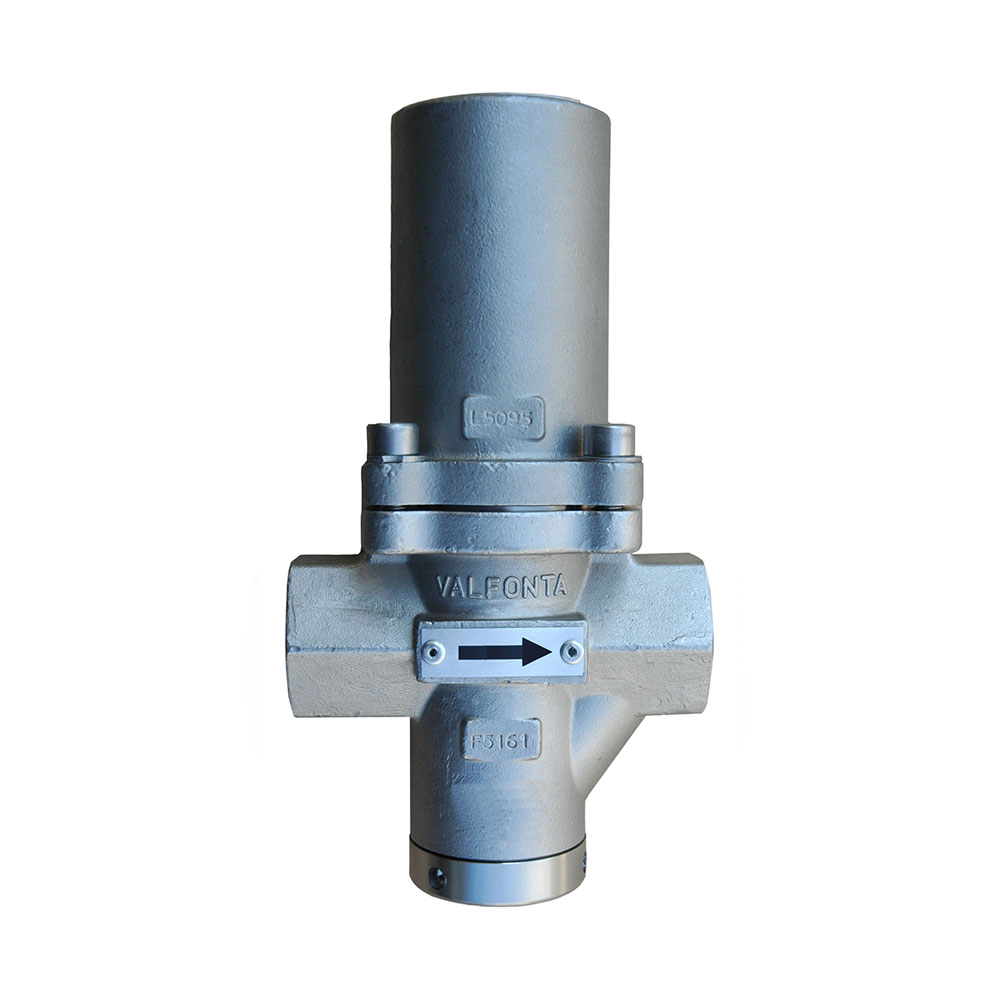 PRV44 reducing valveDN15–25, steam up to 210 °C.
 PRV45 reducing valveOutlet pressures from 0.01 barg; suitable for steam.
 VD reducing valveDN15–100, 40 bar, and steam up to 200 °C.
 PRV30 reducing valve316L stainless, DN15–25.
 PRV20 reducing valve316L stainless, DN8–20 and 40 bar.
Request a quote for the M1
Give us your installation details and we will recommend the size, the actuator, and whether you need a condensate pot.
- Fluid and operating temperature
- Inlet pressure and desired outlet pressure
- Maximum and minimum flow rate
- Size, connection, and body material
You can also call 933 720 888.